Art MX624 Manuel utilisateur
MX624
Six Channel Stereo Mixer with Two Zone Outputs
USER'S GUIDE

2
IMPORTANT SAFETY INSTRUCTIONS - READ FIRST
This symbol, wherever it appears, This symbol, wherever it appears, alerts
alerts you to the presence of uninsulated you to important operating and
dangerous voltages inside the enclosure maintenance instructions in the
that may be sufficient to constitute a risk. accompanying literature. Please read
of shock the manual.
Read instructions Retain these safety and operating instructions for future reference. Heed
all warnings printed here and on the equipment. Follow the operating instructions printed in
this user guide.
Do not open There are no user serviceable parts inside. Refer any service work to qualified
technical personnel only.
Power sources nly connect the unit to mains power of the type described in this user guide
or marked on the rear panel. The power source must provide a good ground connection.
Power cord Use the power cord with sealed mains plug appropriate for your local main
supply as provided with the equipment. If the provided plug does not fit into you outlet consult
your service agent. Route the power cord so that it is not likely to be walked on, stretched or
pinched by items placed upon or against.
Grounding Do not defeat the grounding and polarization means of the power cord plug. Do
not remove or tamper with the ground connection on the power cord.
Moisture To reduce the risk of fire or electrical shock, do not expose the unit to rain,
moisture or use in damp or wet conditions. Do not place containers of liquid on it, which may
spill into any openings
Heat Do not locate the unit in a place close to excessive heat or direct sunlight, as this could
be a fire hazard. Locate the unit away from any equipment which produces heat, such as
power supplies, power amplifiers and heaters.
Environment Protect from excessive dirt, dust, heat, and vibration when operating and
storing. Avoid tobacco ash, drink spillage and smoke, especially that associated with smoke
machines.
Handling Protect the controls from damage during transit. Use adequate padding if you need
to ship the unit. To avoid injury to yourself or damage to the equipment, take care when lifting,
moving or carrying the unit.
Servicing Switch off the equipment and unplug the power cord immediately if it is exposed to
moisture, spilled liquid or the power cord or plug becomes damaged during a lightning storm
or if smoke odor or noise is noted. Refer servicing to qualified technical personnel only.
Installation Install the unit in accordance with the instructions printed in the user guide.

3
OVERVIEW
The ART MX624 Six Channel Stereo Mixer with Two Zone Outputs is a versatile
rack mount mixer that combines six independent stereo input channels and routes
them to two stereo zone outputs. The first three input channels can also accept a
balanced mono XLR microphone input. +48 olt phantom power may be independently
selected on each of the mic inputs. The first channel's mic input can be used to control,
when enabled by a front-panel switch, the ducking of all other channels. All six
channels can accept unbalanced stereo line-level signals. Each channel has
independent level controls and can be independently routed to either zone output, both
or neither. Separate level, bass and treble controls adjust the sound of each zone
output. Two bus inputs allow patching of multiple units when more input channels are
needed.
The ART MX624 may be used on stage, in the studio, or for permanent install
applications including conference rooms, corporate boardrooms, churches,
restaurants, small clubs, health clubs and more. A built-in power supply and single high
19-inch rack mount format allows for easy installation and reliable long-term operation.
Features
•
Six stereo input channels with individual level controls using RCA phono jacks
•
Balanced mono microphone XLRs also available on the first three channels
•
Selectable padding on microphone inputs
•
Full +48 low-noise phantom power independently switchable for each mic input
•
First channel's mic input provides switchable ducking of other channels with
selectable parameters
•
Front panel 1/8-inch stereo (TRS) mini-phone plug for portable music player input
•
Two sets of left and right 1/4-inch mono (TS) main output jacks with master level,
bass and treble controls
•
Two bus input 1/4-inch mono (TRS) jacks allow units to be chained to provide extra
inputs
•
Rugged 1U rack-mount steel chassis with built-in power supply
•
Perfect for stage, studio and permanent installations
•
Three year warranty

4
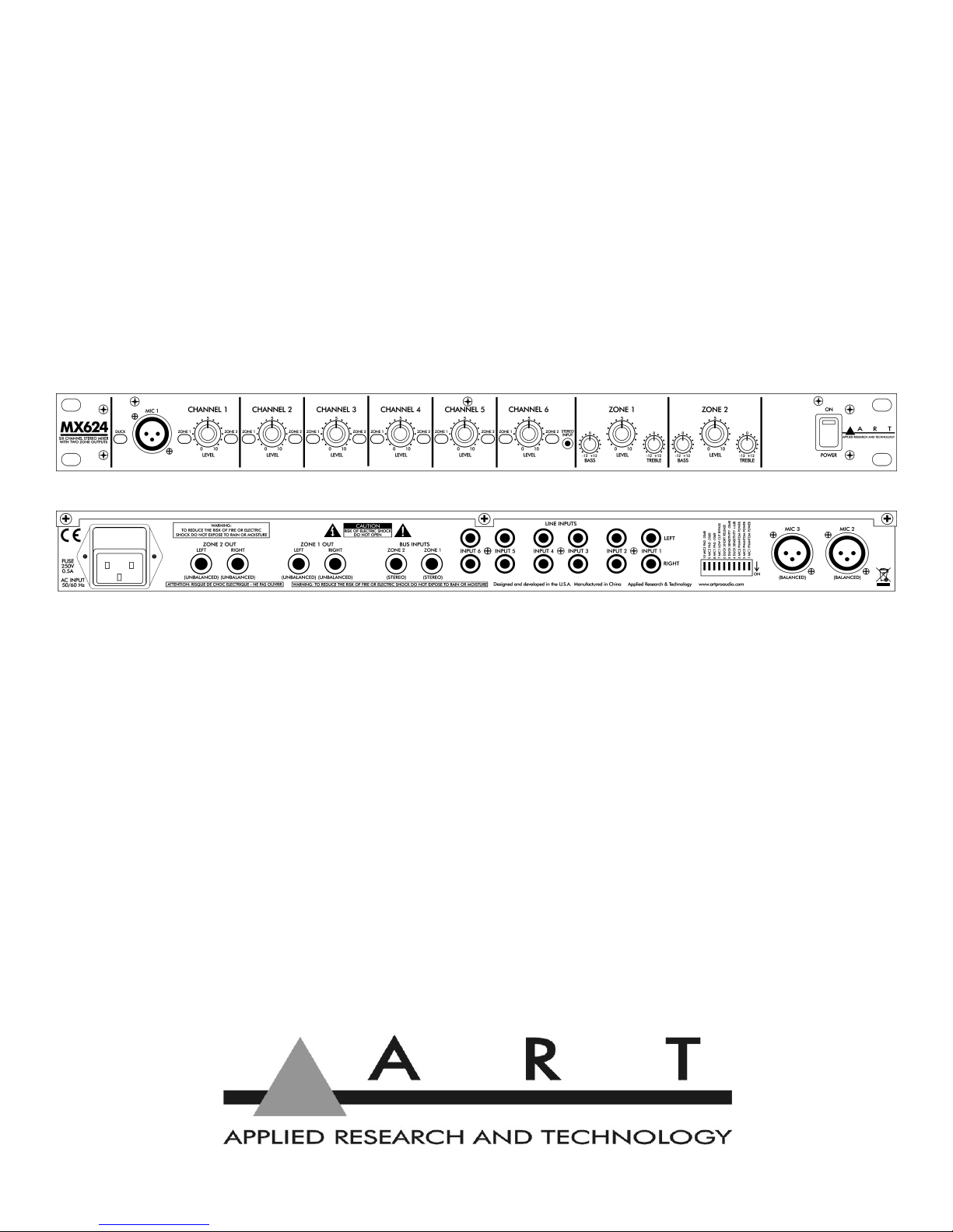
CONNECTIONS
Rear Panel Connections
Inputs
MIC 2 and MIC 3
Each of these two female XLR connectors provides a balanced mono input for a
microphone, which typically outputs lower signal levels. An additional 26 dB of gain is
provided to boost the mic signal to near line level. The mono signal of each mic input is
fed to both left and right stereo channels and mixed with the line-level input signals
from the RCA jacks of the same channel. This combined signal may be assigned to
either Zone 1 or Zone2.
+48 phantom power is available to operate those microphones that contain active
electronic circuitry (such as condenser mics) and may be applied by setting the
corresponding P ANTOM POWER switch in the down (ON) position. The switches are
located towards the right of the rear panel. See page 8 (Rear Panel Controls) for
more information. Note: Do not apply phantom power unless the microphone is
designed to use it.
LINE INPUT 1 through 6 (LEFT and RIG T)
Each of these six stereo pairs of RCA phono jacks provide unbalanced inputs for line
level signals. The top row of jacks is for left channel connections and the bottom row is
for right channel connections.
ZONE 1 and 2 BUS INPUTS
These stereo (TRS) phone jacks provide a direct buffered input connection to the
MX624's internal zone buses. They can be used to chain multiple MX624's together,
using special cables with dual 1/4-inch mono (TS) phone plugs connected to a single
1/4-inch stereo (TRS) phone plug (tip is left and ring is right). Be sure the connections
use shielded cable. Then simply connect the ZONE 1 or 2 OUT (or both) jacks of one
MX624 to the ZONE 1 or 2 BUS INPUT (or both) jacks of another MX624.

5
Additionally, the ZONE 1 and 2 BUS INPUTS may come in handy as extra stereo
inputs. Note, however, that these inputs do not have their own level control and the
zone assignment is hard-wired.
Outputs
ZONE 1 and 2 OUT (LEFT and RIG T)
These four 1/4-inch mono (TS) jacks provide a stereo signal from each of the two
zones of your MX624 to destination devices, such as amplifiers, powered speakers, or
main mixers. These outputs are directly affected by the ZONE 1 and 2 LEVEL
controls, as well as the associated BASS and TREBLE controls. Use shielded cables
with 1/4-inch mono (TS) plugs to connect to these outputs.
Front Panel Connections
Inputs
MIC 1
This female XLR connector is similar to the two rear panel XLR connectors in all
respects, with one important exception. A signal input here can be used to lower the
volume of, or "duck", the other five input channels before they are routed to the zone
outputs. A typical application would be the lowering of the music volume in a restaurant
to announce that someone's table is ready.
The Operation section contains information on the front-panel DUCK switch, which
enables or disables ducking, and a description of the rear-panel DIP switches which
provide options for modifying ducking behavior.
C ANNEL 6 STEREO INPUT
The mini stereo phone jack (1/8-inch TRS) provides a handy input for the signal from
an MP3 player, phone or tablet. It is connected in parallel to the rear-panel stereo RCA
phone jacks.
Refer to the BLOCK DIAGRAM on pages 10 and 11 for more information on how
these connections are routed internally.

6
OPERATION
Front Panel Controls
DUCK Switch
Pushing this switch in enables ducking in response to the signal from the MIC 1 input.
Pushing this switch again returns it to the out position and disables ducking. The switch
is illuminated by a red LED that is part of the ducking circuit, so it provides useful
feedback about the amount of ducking applied as well as indicating basic on/off status.
With ducking enabled, the LED is dimly lit at the onset of ducking with relatively low
level microphone signals. With higher level microphone signals, ducking becomes
more fully engaged and the LED becomes brighter. Note that the LED lights briefly
when power is first applied, even if there is no microphone signal or the switch is in the
out (disabled) position. This power-on ducking helps prevent unwanted noise.
C ANNEL Controls (1-6)
LEVEL
Each of these controls adjusts the level of the associated input channel and
determines its contribution to the overall mix. Unused inputs should have their
associated level control turned off (0 position or fully counterclockwise) to minimize
potential stray noise pickup.
Keep in mind that the best noise performance, while keeping distortion to a minimum,
is obtained with each control adjusted to the maximum desired level (towards 10. In
other words, in general, keep the C ANNEL LEVEL controls turned up and turn the
ZONE LEVEL controls down to compensate, rather than the opposite.

7
ZONE 1 / ZONE 2 Assign Buttons
There are two zone assign buttons for each channel. When both of these buttons are
in the out position, that channel's signal does not get routed to either zone. Pushing the
ZONE 1 button in assigns that channel's signal to Zone 1, where it is mixed with any
other signals assigned to Zone 1. Pushing the ZONE 2 button assigns that channel's
signal to Zone 2, where it is mixed with any other signals assigned to Zone 2. Pushing
both buttons in assigns that channel's signal to both zones. Pushing the buttons again
returns them to the out position.
ZONE 1 and ZONE 2 Output Controls
LEVEL Control
This control adjusts the overall level of the mixed signal output to the ZONE 1 OUT and
ZONE 2 OUT (LEFT and RIG T) jacks.
BASS Control
This control adjusts the bass or low-frequency levels of the output signal. Turning the
control fully counterclockwise applies the maximum bass cut (-12 dB). Turning the
control fully clockwise applies the maximum bass boost (+12 dB). With the control in
the center detent position, the bass response is flat.
TREBLE Control
This control adjusts the treble or high-frequency levels of the output signal. Turning the
control fully counterclockwise applies the maximum treble cut (-12 dB). Turning the
control fully clockwise applies the maximum treble boost (+12 dB). With the control in
the center detent position, the treble response is flat.
POWER Switch
This switch turns the MX624 on and off. When the switch is pushed in at the top (ON
position), a red LED in the switch lights, indicating that power is applied. Pushing the
switch in at the bottom turns the unit off.

8
Rear Panel Controls
There is a group of ten DIP switches located towards the right end of the back panel,
when viewed from the rear. These switches are nominally all in the up or OFF position.
Their function is described below.
Rear Panel DIP Switches
MIC P ANTOM POWER Switches (1-3)
These numbered switches control the application of phantom power (+48 ) to the
corresponding numbered MIC XLR connectors. In the OFF position (up), no phantom
voltage is applied. Moving the switch down (ON position) applies phantom voltage.
Note that when phantom voltage is applied, the current supplied is limited to 7 mA for
each leg of the balanced line.

9
DUCK Control Switches (4-6)
These switches allow you to alter the operation of the ducking action. The two
sensitivity switches adjust the level which the signal from MIC 1 needs to exceed for
ducking to occur. Moving just switch 4 (DUCK SENSITIVITY +6dB) down (ON
position) makes the ducking detector 6dB more sensitive, so that ducking occurs with a
lower mic level. Moving just switch 5 (DUCK SENSITIVITY -20dB) down makes the
ducking detector 20dB less sensitive, so that ducking occurs with a higher mic level.
Both switches could be used together to make ducking 14dB less sensitive. Note that
switch 8 (MIC1 PAD -20dB), discussed below, also affects the ducking level, making it
another 20dB less sensitive.
Switch 6 (DUCK S ORT RELEASE), when in the ON position, makes the ducking
circuit release more quickly, returning the output to normal levels in a shorter amount
of time.
MIC Control Switches (7-10)
Switch 7 (MIC1 LOW CUT BYPASS), when in the ON position, removes the low-
frequency roll-off normally applied to the Mic 1 signal. This roll-off is designed to
remove subaudible noise, such as mechanical clicks and thumps, that might falsely
trigger the ducking circuitry.
Switches 8 through 10 (MIC1,2,3 PAD -20dB), when in the ON position, pad the
corresponding microphone input or make them 20dB less sensitive. This could be
useful with high-output microphones to prevent overdriving or clipping the inputs. Note
that the Mic 1 pad (switch 8) also affects the level applied to the ducking circuitry, as
mentioned above.

10
BLOCK DIAGRA
Table des matières
Autres manuels Art Matériel de musique

Art
Art HeadTAP Manuel utilisateur

Art
Art ARTcessories DUAL RP Manuel utilisateur

Art
Art PDB Manuel utilisateur

Art
Art PDB Manuel utilisateur

Art
Art PDB4 Manuel utilisateur

Art
Art DPDB Guide de l'utilisateur

Art
Art TPatch Artcessories Manuel utilisateur

Art
Art CleanBOX II Manuel utilisateur

Art
Art dPDB Manuel utilisateur


