Array electronic TC-Pro482 Series Manuel utilisateur

Ver:3.0

1
Multifunction LCD Digital Timer/Counter/Tachometer
Multifunction LCD Digital Timer/Counter/Tachometer
TC-Pro482×××
Highly visible display with backlit negative transmissive LCD
Visual alert when output status changes
PNP/NPN switchable DC-voltage input
Finger-safe terminals(screw terminal block models)
Three-language instruction manual
Applied to connect PC/HMI
Contents
Model Number Structure....................................................2
Specifications.....................................................................3
Nomenclature.....................................................................6
Operating Procedures........................................................9
Timer Function .................................................................12
Twin Timer Function.........................................................15
2-Stage Timer Function....................................................17
Counter Function .............................................................20
Tachometer Function .......................................................23
Sequence Charts .............................................................26
Dimensions ......................................................................38
Input Connections ............................................................40
Safety Precautions...........................................................42
Additional Information ......................................................44
List of Settings .................................................................47
■
■
■
■
■
■

2
Multifunction LCD Digital Timer/Counter/Tachometer
Model Number Structure
List of Models
Output type Supply voltage
Model
Standard Communication
Contact output 100~240 VAC TC-Pro482SRA (-D) TC-Pro482CRA (-D)
24 VDC/24 VAC TC-Pro482SRD (-D) TC-Pro482CRD (-D)
Transistor output 100~240 VAC TC-Pro482STA (-D) TC-Pro482CTA (-D)
24 VDC/24 VAC TC-Pro482STD (-D) TC-Pro482CTD (-D)
Note: The model with communication must be used with cable.
Model Number Legend
TC-Pro 482 -
1 2 3 4
Accessories (Order Separately)
Name Models
9-pin Female D-sub cable for RS-232 connector, 1.5m Cable CAB-090A232
9-pin Female D-sub cable for RS-485 connector, 1.5m Cable CAB-090A485
9-pin Female D-sub cable for RS-422 connector, 1.5m Cable CAB-090A422
9-pin male D-sub adapter for
CAB-090A232/CAB-090A485/CAB-090A422 ADP-090401
9-pin Female D-sub cable for RS-232 connector, 1.5m Cable CAB-090B232
9-pin Female D-sub cable for RS-485 connector, 1.5m Cable CAB-090B485
9-pin Female D-sub cable for RS-422 connector, 1.5m Cable CAB-090B422
Mounting Track 0F-A
Panel Protective Cover SVF-A
Communication Protective Cover TTL-11
Note:CAB-090A232/485/422 is used for Flush mounting products
CAB-090B232/485/422 is used for DIN track mounting products
■
■
■
1. Communication
S: Standard (no communication)
C: Communication
2. Output type
R: Contact
T: Transistor
3. Supply voltage
A: 100V~240VAC
D: 24VDC、24VAC
Mounting method
None: Flush mounting
D: DIN track mounting
4.
3
Multifunction LCD Digital Timer/Counter/Tachometer
Specications
Ratings (For Timing)
Item TC-Pro482□□□-□
Classication Digital timer/counter/tachometer
Rated supply voltage 100~240VAC (50/60Hz), 24VAC (50/60Hz), 24VDC (permissible ripple:20% (p-p) max.)
Operating voltage
range 85% to 110% rated supply voltage (24VDC; 90% to 110%)
Power consumption
Approx. 6.2VA at 264VAC,
Approx. 5.1VA at 26.4VAC,
Approx. 2.4W at 24VDC
Mounting method Flush mounting, DIN track mounting
External connections Screw terminals
Terminal screw
tightening torque 0.5 N•m Max.
Display
7-segment, LCD display
Present value: 9-mm-high characters, white
Set value: 4-mm-high characters, white
Digits 6 digits
Time range
999.999s (0.001-s unit), 9999.99s (0.01-s unit), 99999.9s (0.1-s unit)
999999s (1-s unit), 9999min59s (1-s unit), 99999.9min (0.1-min unit),
999999min (1-min unit), 9999h59min (1-min unit), 99999.9h (0.1-h unit), 999999h (1-h unit)
Timer mode Elapsed time (UP), Remaining time (down) (selectable)
Input signals Signal, reset, gate
Input method
No-voltage input/voltage input (switchable)
No-voltage input
ON impedance: 1kΩ max. (leakage current: 5~20 mA at 0Ω)
ON residual voltage: 3V max.
OFF impedance: 100kΩ min.
Voltage Input
High (logic) level: 4.5 to 30 VDC
Low (logic) level: 0 to 2 VDC
(Input resistance: approx. 4.7 kΩ)
※
◆
◆
Signal, Reset, Gate Minimum input signal width: 1 or 20 ms (selectable, same setting for all inputs)
Power reset Minimum power-opening time: 0.5 s (exceptA-3、b-1 and F mode)
Reset system Power reset (execptA-3、b-1and F mode), external and manual reset
Sensor waiting time 250 ms max. (control output is turned OFF and no input is accepted during sensor waiting
time)
Output modes A, A-1, A-2, A-3, b, b-1, d, E, F, Z, ton or toff
One-shot output time 0000.01~9999.99s
Output method Relay/transistor output
Control output
SPDT contact output: 5A at 250 VAC, resistive load (cosФ=1)
Minimum applied load: 10 mA at 5 VDC (failure level: P, reference value)
Transistor output: NPN open collector, max. 100mA at 30 VDC
Residual voltage: 1.5 VDC max. (approx. 1V)
Output category according to EN60947-5-1 for timers with Contact outputs
(AC-15; 250V 3A / AC-13; 250V 5A / DC-13; 30V 0.5A)
Output category according to EN60947-5-2 for timers with Transistor outputs
(DC-13; 30V 100 mA)
NEMA B300 Pilot Duty, 1/4 HP 5-A resistive load at 120 VAC, 1/3 HP 5-A resistive load at
240 VAC
External power supply 12VDC (15%), 80mA
Key protection Yes
Memory backup EEPROM (overwrites: 100,000 times min.) that can store data for 10 years min.
■
4
Multifunction LCD Digital Timer/Counter/Tachometer
Ratings (For Counting)
Item TC-Pro482□□□-□
Classication Digital timer
Supported
congurations
1-stage counter, 2-stage counter, total counter, batch counter, dual counter, and tachometer
(selectable)
Rated supply voltage 100~240VAC (50/60Hz), 24VAC (50/60Hz), 24VDC (permissible ripple: 20% (p-p) max.)
Operating voltage
range 85% to 110% rated supply voltage(24VDC; 90% to 110%)
Power consumption
Approx. 6.2VA at 264VAC,
Approx. 5.1VA at 26.4VAC,
Approx. 2.4W at 24VDC
Mounting method Flush mounting, DIN track mounting
External connections Screw terminals
Terminal screw
tightening torque 0.5 N•m Max.
Display
7-segment, LCD display
Present value: 9-mm-high characters, white
Set value: 4-mm-high characters, white
Digits 6 digits, PV/SV (-99,999~999,999)
Input method CP1, CP2, reset1, and reset 2
Max. counting speed 30 Hz or 5kHz (selectable, ON/OFF ratio 1:1), common setting for CP1 and CP2
Input mode Increment, decrement, command, individual, and quadrature
Input method
No-voltage input/voltage input (switchable)
No-voltage input
ON impedance: 1kΩ max. (leakage current: 5~20 mA when 0Ω)
ON residual voltage: 3V max.
OFF impedance: 100kΩ min.
Voltage Input
High(logic) level: 4.5 to 30 VDC
Low(logic) level: 0 to 2 VDC
(Input resistance: approx. 4.7 kΩ)
※
◆
◆
Reset input Minimum input signal width: 1/20 ms (selectable, same settingfor all inputs)
Reset system External, manual, and automatic reset (internal according to C,R,P and Q mode operation)
Output modes N,F,C,R,K-1,P,Q,A,K-2,D,L,H
One-shot output time 000.001~9999.99s
Output method Relay/transistor output
Control output
SPDT contact output: 5A at 250 VAC, resistive load (cosФ=1)
Minimum applied load: 10 mA at 5 VDC (failure level: P, reference value)
Transistor output: NPN open collector, max. 100mA at 30 VDC
Residual voltage: 1.5 VDC max. (approx. 1V)
Output category according to EN60947-5-1 for timers with Contact outputs
(AC-15; 250V 3A / AC-13; 250V 5A / DC-13; 30V 0.5A)
Output category according to EN60947-5-2 for timers with Transistor outputs
(DC-13; 30V 100 mA)
NEMA B300 Pilot Duty, 1/4 HP 5-A resistive load at 120 VAC, 1/3 HP 5-A resistive load at 240
VAC
External power supply 12VDC(15%), 80mA
Key protection Yes
Prescaling function Yes (000.001~999.999)
Decimal point
adjustment Yes (rightmost 3 digits)
Sensor waiting time 250 ms max. (Control output is turned OFF and no input is accepted during sensor waiting
time.)
Memory backup EEPROM (overwrites: 100,000 times min.) that can store data for 10 years min.
Ambient temperature Operating: -10 to 55°C (with no icing or condensation)
Storage: -25 to 65°C (with no icing or condensation)
Ambient humidity 25% to 85%
Case color Flush mode: black, DIN track mode: gray-black
Attachments Waterproof packing, ush mounting adapter
■

5
Multifunction LCD Digital Timer/Counter/Tachometer
Characteristics
Item TC-Pro482□□□-□
Life expectancy Mechanical: 10,000,000 operations min.
Electrical: 100,000 operations min. (5 A at 250 VAC, resistance load)
EMC
(EMI)
Emission Enclosure:
Emission AC mains:
(EMS)
Immunity ESD:
Immunity RF-interference:
Immunity Conducted Disturbance:
Immunity Burst:
Immunity Surge:
Immunity voltage Dip/interruption:
EN61326
EN55011
EN55011
EN61326
EN61000-4-2
EN61000-4-3
EN61000-4-6
EN61000-4-4
EN61000-4-5
EN61000-4-11
Weight Approx. 168g
■
6
Multifunction LCD Digital Timer/Counter/Tachometer
Nomenclature
Reset Operation by Reset Key
Conguration Reset operation
1-stage/2-stage counter Resets the present value and outputs
Total counter
Resets the present value and outputs
When the total count value is displayed, resets the present value, the total count value, and
outputs.
Batch counter
Resets the present value and OUT1
When the batch count value is displayed, resets the present value, the batch count value, and
outputs.
Dual counter Resets the CP1 present value, CP2 present value, dual count value and outputs
tachometer Maintains the measured value and outputs
■
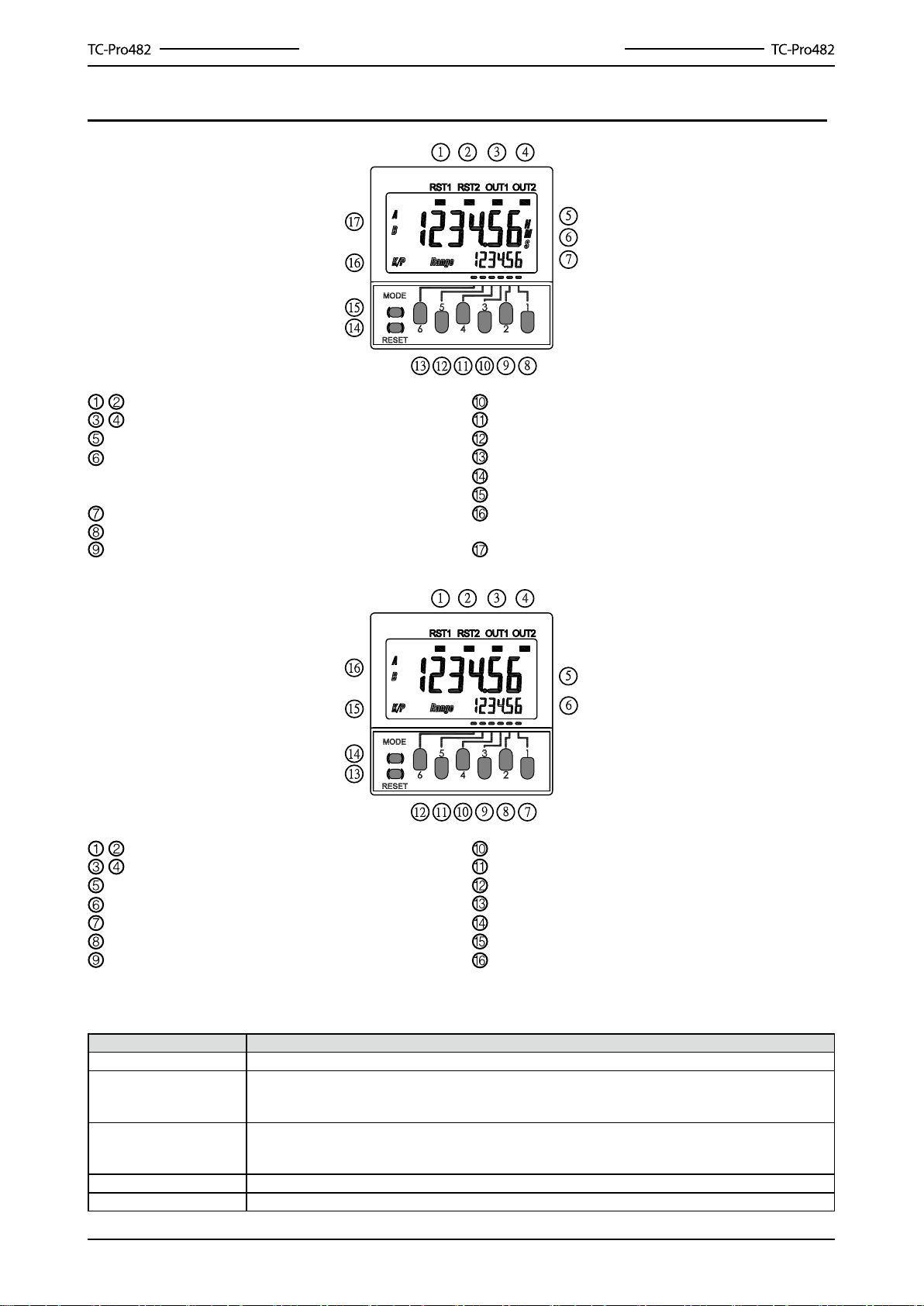
Reset Indicator
Control Output Indicator
Present Value (character height: 9 mm)
Time Unit Display (If the time range is 0 min,
0.0 min, 0 h, 0.0 h, 0h0 min, this display ashes
to indicate timing operation)
Set Value (character height: 4 mm)
The First Setting Key
The Second Setting Key
The Third Setting Key
The Fourth Setting Key
The Fifth Setting Key
The Sixth Setting Key
Reset Key (resets present value and output)
Mode Key (changes modes and setting items)
Key Protection Indicator (the preset value is
OFF)
Set Value (Range) A, B Display
Reset Indicator
Control Output Indicator
Present Value (character height: 9 mm)
Set Value (character height: 4 mm)
The First Setting Key
The Second Setting Key
The Third Setting Key
The Fourth Setting Key
The Fifth Setting Key
The Sixth Setting Key
Reset Key (resets present value and output)
Mode Key (changes modes and setting items)
Key Protection Indicator (the preset value is OFF)
Set Value (Range) A, B Display

7
Multifunction LCD Digital Timer/Counter/Tachometer
Block Diagram
Output circuit
Basic isolation
Display circuit
Key switch circuit
Input circuit Internal control circuit
Power supply circuit
Basic isolation
I/O Functions (Timer/Twin Timer)
Input
Start signal Stops timing in A-2 and A-3 (power ON delay) modes
Starts timing in other modes
Reset
Reset present value (In elapsed time mode, the present value returns to 0; in
remaining time mode, the present value returns to the set value)
Count inputs are not accepted and control output turns OFF while reset input
is ON.
Reset indicator is lit while reset input is ON.
Gate Inhibits timer operation
Outputs Control output
(OUT)
Outputs take place according to designated operating mode when timer
reaches corresponding set value.
Note: Two control outputs can be used.
I/O Functions (2-Stage Timer)
Inputs
Start signal Starts timing
Reset
Resets present value (the present value returns to 0)
Timing inputs are not accepted and control output turns OFF while
reset input is ON.
Reset indicator is lit while reset input is ON.
Gate Inhibits timer operation
Outputs
Forecast
value
setting
Control output
(OUT2) Turn ON when the present value reaches the set value.
Forecast output
(OUT1)
Turn ON when the present value reaches the forecast value.
The forecast value=set value-forecast set value
Absolute
value
setting
Control output 2
(OUT2) Turn ON when the present value reaches the set value 2.
Control output 1
(OUT1) Turn ON when the present value reaches the set value 1.
■
■
■

8
Multifunction LCD Digital Timer/Counter/Tachometer
I/O Functions (Counter)
Inputs
CP1, CP2
In general (except for dual counter mode)
Reads counting signals
Increment, decrement, command, individual, and quadrature inputs
accepted.
When used as a dual counter
Reads CP1 count signals with CP1 input and CP2 count signals with
CP2 input.
Increment signals can be input.
1.
2.
Reset or Reset 1
In general (except for dual counter mode)
Resets present value and outputs
Counting can not be performed during reset/reset 1 input
The 3reset indicator is lit during reset input.
When used as a dual counter
Resets CP1 present value
Counting for CP1 input can not be performed during reset 1 input.
The reset indicator is lit during reset 1 input.
1.
2.
Total Reset or Reset 2
(see note 2.)
When used as 1-stage/2-stage counter
Does not operate (Not used).
When used as a total and present counter
Resets the total count value
Hold the total count value at 0 during total reset input
When used as a batch counter
Reset the batch count value and batch output (OUT1)
Holds the batch count value at 0 during total reset 2 input
When used as a dual counter
Resets the CP2 present value
Counting for CP2 input can not be performed during reset 2 input
1.
2.
3.
4.
Output Control output
(OUT)
Outputs take place according to designated output mode when
corresponding preset is reached.
Note:
In increment mode or increment/decrement mode, the present value returns to 0, in decrement mode,
the present value returns to the set value with 1-stage models, and returns to set value 2 with 2-stage
models.
The reset indicator will not be lit when the total reset or reset 2 input is ON.
I/O Functions (Tachometer)
Inputs
CP1, CP2 Reads counting signals. (CP2 input is not used)
RESET1, RESET2 Holds the measurement value and outputs. (CP2 input is not used)
The reset indicator is lit during hold.
Outputs OUT1, OUT2 Outputs signals according to the specied output mode when a set value
is reached.
■
1.
2.
■

9
Multifunction LCD Digital Timer/Counter/Tachometer
Operating Procedures
Timer/Twin Timer/2-stage Timer Selection Mode
Power ON
Note: when the mode is changed to timer/twin timer/2-stage timer
selection mode, the present value is reset and output turns OFF.
See noteSee note
3s min.
3s min.
Tachometer setting mode
(See Run Mode on page 23)
Timer setting mode
(See Run Mode on page 12)
Twin Timer setting mode
(See Run Mode on page 15)
Twin Forecast setting mode
(See Run Mode on page 17)
1-stage counter setting mode
(See Run Mode on page 20)
2-stage counter setting mode
(See Run Mode on page 20)
Dual counter setting mode
(See Run Mode on page 29)
Batch counter setting mode
(See Run Mode on page 35)
Total counter setting mode
(See Run Mode on page 35)
Run Mode
Timer/Twin Timer/Twin Forecast Timer/1-stage/2-stage/total/batch/dual counter/tachometer Selection Mdoe
■
Ce manuel convient aux modèles suivants
16
Table des matières
Autres manuels Array electronic Minuteur


