Ariston SOLARcomfort Guide de l'utilisateur

SOLARcomfort
Solar Hot Water
Systems
Pump Group Instructions for Installation
and Servicing
LEAVE THESE INSTRUCTIONS WITH THE
END USER
Country of Destination GB/IE

1
TABLE OF CONTENTS
1. GENERAL INFORMATION ................ 2
1.1 GUARANTEE .......................................... 2
1.2 SYSTEM CONTENTS ................................ 2
1.3 SYSTEM INSTRUCTION BOOKS ................... 2
1.4 SOLARCOMFORT .................................. 3
1.5 LIFESTYLE ............................................. 3
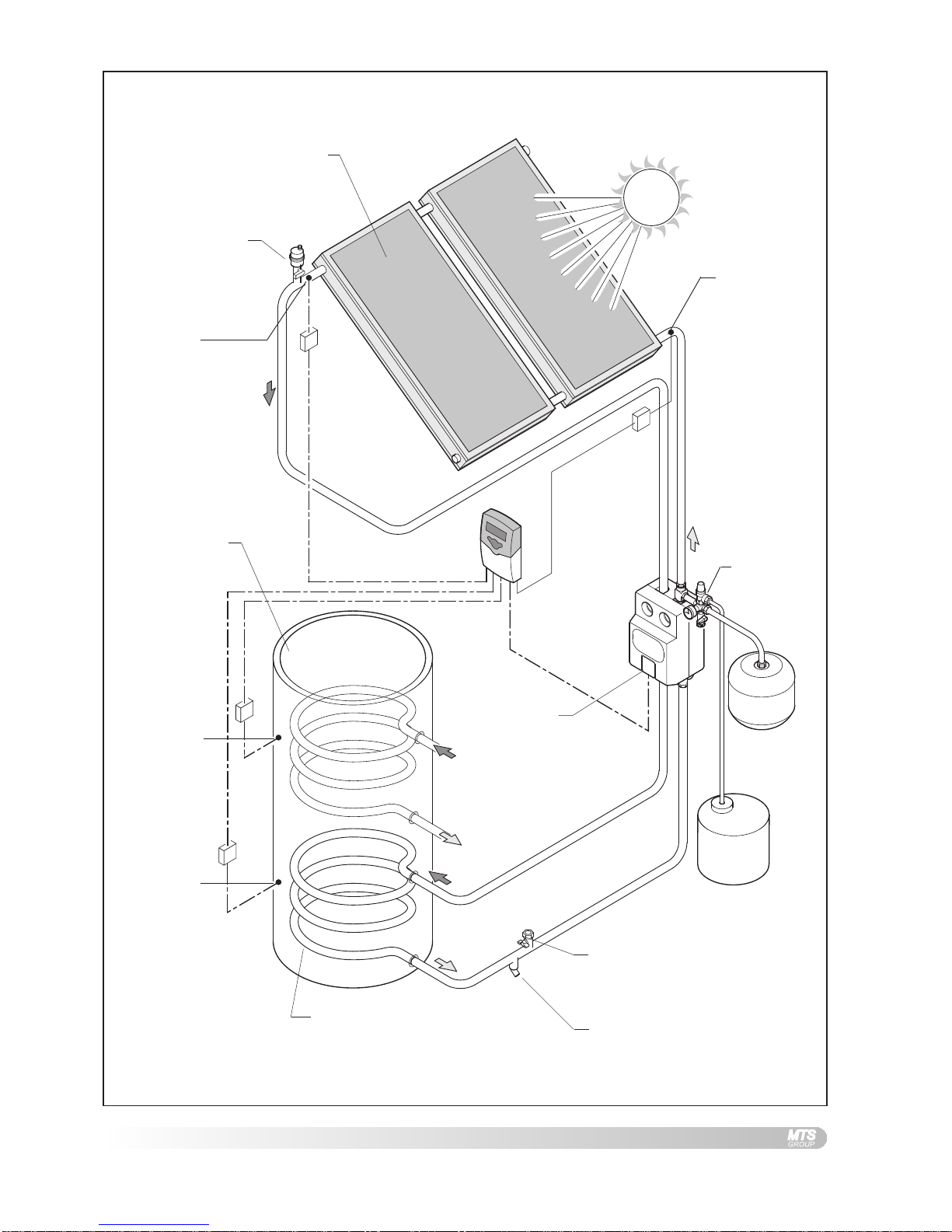
1.6 HOW THE SYSTEM WORKS ....................... 3
2. SAFETY ............................................. 6
3. TECHNICAL DATA ............................. 7
3.1 TEMPERATURE/PRESSURE ........................ 7
3.2 COMPONENT LIST ................................... 8
3.3 PUMP GROUP DIMENSIONS ...................... 9
3.4 EXPANSION VESSEL DIMENSIONS ............... 9
4. REGULATIONS & STANDARDS...... 10
4.1 WAT E R REGULATIONS ........................... 10
4.2 BUILDING REGULATIONS ......................... 10
4.3 GENERAL GUIDANCE ............................. 10
4.4 BRITISH & EUROPEAN STANDARDS .......... 11
4.5 UK REGULATIONS (WAT E R HEATING) ...... 11
4.6 UK REGULATIONS (CONSTRUCTION) ........ 11
4.7 EU DIRECTIVES ................................... 12
4.8 OTHER PUBLICATIONS ........................... 12
4.9 ELECTRICAL CONNECTION ...................... 12
4.10 THERMAL INSULATION ............................ 12
5. INSTALLATION ................................ 13
5.1 FITTING FLOW LIMITER .......................... 13
5.2 POSITIONING PUMP GROUP .................... 13
5.3 CONSIDERATIONS FOR POSITIONING PUMP
GROUP ............................................... 14
5.4 PIPEWORK AND FITTINGS ....................... 14
5.5 INSULATION .......................................... 14
5.6 SIZING OF PIPES .................................. 15
5.7 PIPEWORK ........................................... 15
5.8 ELECTRICAL CONNECTIONS .................... 15
5.9 TWO COLLECTOR SCHEMATIC ................. 17
5.10 THREE COLLECTOR SCHEMATIC .............. 17
5.11 WALL MOUNTING MODULES ................... 18
5.12 CONNECTING PIPEWORK ........................ 19
5.13 PIPE REDUCERS .................................. 20
5.14 EXPANSION VESSEL .............................. 20
5.15 PRESSURE RELIEF VALVE ...................... 21
5.16 FILLING POINT ..................................... 22
5.17 FLOW REGULATOR ................................ 22
6. COMMISSIONING SYSTEM ........... 23
6.1 PRE-FILL CHECK .................................. 23
6.2 FLUSHING AND FILLING THE SYSTEM USING
GLYCOL .............................................. 24
6.3 FLUSHING THE SYSTEM USING WATER ...... 26
6.4 FILLING AND TOPPING UP THE SYSTEM WITH
GLYCOL .............................................. 28
6.5 SYSTEM PRESSURE .............................. 30
6.6 COMMISSIONING SHEET ......................... 31
7. MAINTENANCE SCHEDULE .......... 32
this will be page 1

2
1. GENERAL
INFORMATION
This manual is an integral and essential part of the product. It should be
kept with the product.
Please read carefully the instructions and notes about SOLARcomfort
contained in this manual as they provide important information regarding
the safe installation of the Pump Group.
IMPORTANT
Failure to follow these instructions correctly may invalidate the
guarantee.
IMPORTANT
Solar domestic hot water heating systems must be installed to
comply with the current Building Regulations, British Standards
and any applicable local regulations.
The SOLARcomfort Pump Group is guaranteed for 2 years against
munufacturing defect - see terms and conditions of guarantee on back
page.
The complete SOLARcomfort solar water heating system is supplied in
the following consignments:-
1. Ref. 800201 Collector 1 per box
2. Ref. 3107024/5 Roof Fittings Kit 1 cardboard tube
3. 3820011/2 System Components 1 box
4. 3820001 Tyfocor anti freeze heat transfer fluid
1 x 20l container
The following instruction booklets are supplied with a complete
SOLARcomfort solar water heating system:-
1. SOLARcomfort Solar Hot Water Systems Collectors 2 & 3 Collector
Set.
Covers collector installation and plumbing connection.
Supplied in System Components box.
2. SOLARcomfort Solar Hot Water Systems Pump Group 40/60.
Covers installation, plumbing connection, system filling, flushing and
commissioning.
Supplied in System Components box.
3. Solar Controller AST100
Covers installation, wiring connection and User Instructions.
Supplied in System Components box.
1.1 GUARANTEE
1.2 SYSTEM CONTENTS
1.3 SYSTEM INSTRUCTION BOOKS

3
SOLARcomfort systems are highly efficient and provide cost savings on
the energy used for heating hot water wherever they are used in the UK.
However, the savings made will depend on local climate, installation
characteristics and the households use of hot water.
It is important that the SOLARcomfort system is correctly sized for the
local climate condition and the household’s domestic hot water
requirements.
After installation of the SOLARcomfort system, changes to the
householders use of hot water will be beneficial. Simple changes such as
bathing in the evening instead of the morning, and putting automatic
washing machines on when free hot water is available by solar energy.
In addition, the timing of the dwelling’s boiler controls must be modified to
ensure the ‘hot water ON’ time is set so that the water temperature in the
cylinder is at a minimum by the start of the ‘solar day’.
The solar collectors are heated by the sun’s rays. The heat generated is
stored in a hot water storage cylinder e.g. an Ariston Primo twin coil stainless
steel cylinder. The AST 100 Solar Controller continually compares the
temperature of the water within the cylinder with the temperature of the
solar collectors.
Whenever the solar collectors are hotter than the water within the cylinder,
the controller switches on the system’s circulating pump. The temperature
differential between the collectors and the cylinder is set via the AST100
Solar Controller. The heat transfer fluid within the solar system is then
circulated through the collectors and the cylinder’s heat exchanger, heating
the cylinder in just the same way as a central heating boiler.
The cylinder typically has two coils (heat exchangers), the lower coil is
heated by the solar system, therefore solar is the primary heat source.
The upper cylinder is heated by an auxiliary heat source, typically a central
heating boiler, which is used to heat water when there is insufficient heat
generated by the solar system. The Ariston Primo twin cylinder also has
two immersion heaters making it suitable for electric only heating systems.
The SOLARcomfort system is a forced circulation sealed system and
therefore requires an expansion vessel and a pressure relief valve (PRV),
both supplied with SOLARcomfort.
The air separator with an integral air vent together with an automatic air
vent positioned at the highest point on the system ensures that the sealed
system remains free of air.
1.6 HOW THE SYSTEM WORKS
See fig. 1.6A
1.4 SOLARCOMFORT
1.5 LIFESTYLE

4
FIG. 1.6ABASIC PRINCIPLES
Roof mounted collectors
(two collector system shown)
Pump group
Expansion
vessel
Solar system
low level fill
point
Ariston ITSI 210/300
twin coil cylinder
Upper coil
heated by boiler
or other heat
source
Lower coil heated by
solar energy
AST 100
Controller
Air vent
PR Valve
Solar system
drain point
Temperature
Sensor S1
Temperature
Sensor S3
Temperature
Sensor S2 PRV discharge
vessel
Energy
Monitoring
Sensor S4
(option)

5
FIG. 1.6BPUMP GROUP COMPONENTS
1. Insulated Cover
2. Flow from Solar Collectors
3. Flow Temperature Gauge
4. Flow Shut Off Valve
c/w non return valve -red Knob
5. Air Separator
6. Manual Air Vent
7. Return to Solar Collectors
8. Return Temperature Gauge
9. Return Shut Off Valve
c/w non return valve -blue Knob
10. Circulating Pump
11. System Fill and Drain Point
12. Fill and Drain Shut Off Valve
13. Flow Limiter
14. Flow Limiter Adjustment Screw
15. Non-return Valve
16. Non-return Valve Shut Off
17. Expansion Vessel Connection
18. Pressure Relief Valve (PRV)
19. PRV Outlet
20. System Pressure Guage
ReturnFlow

6
2. SAFETY WARNING
The pump group must be correctly fitted to the wall using the bracket
supplied. It should not be supported by the connecting pipework
alone.
WARNING
During operation and commissioning the temperature of the heat
transfer fluid within the system and collectors can reach temperatures
high enough to present a risk of scalding. Never loosen fittings or
open vents when the system is hot.
WARNING
TYFOCOR LS Heat Transfer Fluid.
Although non-toxic it should not be swallowed.
Refer to label on its container for storage and safety information.
A detailed technical specification is available from Ariston on request.
Caution
SOLARcomfort should be installed and commissioned by approved
contractors. Failure to do so may invalidate the warranty.
Caution
The pump group should be positioned so that it is inaccessible to children
and cannot be tampered with.

7
3. TECHNICAL DATA
Operating pressure and
temperature must be within
the limits depicted by the
hatched area
Operating temperatures above
100°C as depicted by the
shaded area must be avoided
for continuous operation
FIG. 3.1ATEMPERATURE PRESSURE DIAGRAM
3.1 TEMPERATURE / PRESSURE
PUMP MODULE
Pipe connection 22mm
Reducers supplied 15mm
Pump type 15/40
Maximum operating pressure 0.6MPa
Electrical Cable 1.0mm² 3 core heat resistant flex 3093Y to 85°C
Cover Moulded polystyrene
AIR SEPARATOR MODULE
Pipe connection 22mm
Reducers supplied 15mm
Maximum operating pressure 0.6MPa
Cover Moulded polystyrene
EXPANSION VESSEL
2 & 3 collector systems 25l
Optional size (code 12002737) 35l
Maximum pressure 10 bar
Pre-charge pressure 2.5 bar
PRESSURE RELIEF VALVE
Setting 6 bar
Discharge ½” BSP - Ø15 pipe
HEAT TRANSFER FLUID
Type Tyfocor LS
Use undiluted 100%
Weight 1.04kg/l
Frost protection to -28°C

8
3.2 COMPONENT LIST
FIG. 3.2APUMP GROUP COMPONENT LIST
Listed below are all the components required to fit the pump group.
Item Description Qty
1 Pump Group 1
2 Flow Limiter Components (see 5.1) 1 set
3 Wall Mounting Bracket 1
4 Screw 1
5 Wall Plug 1
6 Expansion Vessel 25l standard (35l option) 1
7 Expansion Vessel Fixings 1
8 Flexible Connector 1

9
FIG. 3.3APUMP GROUP DIMENSIONS
FIG. 3.4AEXPANSION VESSEL DIMENSIONS
25 Litre
(standard)
35 Litre
(optional: code 12002737)
3.3 PUMP GROUP DIMENSIONS
3.4 EXPANSION VESSEL DIMENSIONS
Maximum pressure 10 bar
Pre-charge pressure 2.5 bar
Autres manuels pour SOLARcomfort
1
Table des matières
Autres manuels Ariston Pompe à eau
Manuels Pompe à eau populaires d'autres marques

Sykes AmeriPumps
Sykes AmeriPumps GP100M Guide de dépannage

DUROMAX
DUROMAX XP WX Series Manuel utilisateur

BRINKMANN PUMPS
BRINKMANN PUMPS SBF550 Manuel utilisateur

Franklin Electric
Franklin Electric IPS Manuel utilisateur

Xylem
Xylem e-1532 Series Manuel utilisateur

Milton Roy
Milton Roy PRIMEROYAL Manuel utilisateur


