Arduino IN-14 Nixie Manuel utilisateur

Arduino IN-14 Nixie Clock v42
“All-In-One” Clock
Operating Instructions
&
Construction Manual
NixieClockIN14InstructionManualRev2V42

Contact In ormation
If you want to get in contact with us, please e ail to:
nixie@proton ail.ch
We'll usually get back to you right away. We can help you with kits or construction.
We also offer discounts for direct purchases, we save the Ebay fees, and share this with you.
http://www.open-rate.co /Store.ht l
So tware
The software is open source and is available on GitHub at the address:
https://github.co /isparkes/ArdunixNix6/releases
This board works with Release “Revision 4 boards” under the “Releases” tab.
Troubleshooting
If everything does not work as you expect, please carefully look at the tests in the construction steps, and
the troubleshooting tips.
At the end of the anual, there is a troubleshooting section, which goes through so e of the co on
proble s. If you can't work it out, please get in contact with us. We guarantee that you will get going.

Description
The Arduino Nixie Clock is a beautiful ix of old and new, resulting in a high accuracy, low power clock
which will be a talking point in your ho e.
The clock has the following features:
•Latest technology, highly reliable and accurate.
•Tried and tested design, with any hundreds of clocks sold.
•Based on the Arduino icro-controller: Easy to progra an well docu ented.
•Open source hardware and software. Nothing is hidden in this clock. (You ay odify and load the
software).
•Low power consu ption.
•Long tube life: Anti Cathode Poisoning (ACP) and configurable blanking akes sure that the tubes
will stay healthy for any years with no intervention fro you.
•The ultiplexed display and auto atic di ing used in this design extends the life of the tubes
indefinitely. So e other designs run the tubes too “hard”, and this causes a rapid degradation in
the useful life of the tube.
•All settings are stored in non-volatile e ory. Once they are set, they are re e bered forever, or
until you change the again.
•RGB back lighting allows you to set the the color of the back lighting to practically any color you
desire.
•A bient light sensing, with auto atic tube di ing, which sets the tube and LED brightness
according to the light conditions. This also increases tube life.
•Absolutely silent operation. So e Nixie clocks e it an irritating “buzz” or “hiss” which is especially
annoying if you keep the clock in a bedroo .
•Auto atic week day or weekend blanking, extends the life of tubes even further
•Auto atic ti e of day blanking, can blank between a start hour and an end hour, on week days,
weekends or every day
•Configurable suppression of Anti Cathode Poisoning when the clock is fully di ed. In the iddle
of the night, all the digits lighting up at full brightness could be disturbing. You can choose to stop
ACP when the clock is fully di ed
•The High Voltage Generator auto-calibrates itself to atch your tubes and power supply, eaning
that the power consu ption is the lowest possible. (Usually 2W when fully bright, 0.4W when
blanked).
•Highly accurate when using RTC odule:
•Battery backed, te perature co pensated, high accuracy clock. The accuracy is Accuracy
±2pp fro 0°C to +40°C. (Maxi u 1 inute per year).
•The battery life should be 3 years in nor al use.
•Retains the date and ti e even when turned off (not just for a few inutes, but for as long
as the battery lasts)
•Leap Year Co pensation Valid Up to the year 2100
•Extre ely accurate when using the optional Wifi odule:
•The ti e never drifts, is always right to within 1 second.
•Auto atically co pensates for Daylight Savings Ti e changes, leap years and seconds.

General
The clock has different odes of operation, which you select using the pushbutton. When you start the
clock up th very first ti e, it will start in “Ti e Display Mode”. We set it up to be the right ti e for where
the clock is being shipped to, so in the best case you will not even need to set the clock the first ti e!
The other odes of operation are described in the following sections.
Sa ety
The voltages produced in the High Voltage circuit can reach peaks of 400V! Take precautions not to
electrocute yourself! If you are not sure what this eans, please do not use this clock and return it for a
full refund.
A shock fro the clock high voltage circuit is at least a nasty bite. At worst it can kill you.
We decline any responsibility in the case of injury or death.
REPEAT: If you are not sure, please do not use the clock.
Powering Up
When you power the unit up, it will display “88:88:88” for several seconds. This is for the calibration of the
High Voltage Generator to atch the power adapter you have attached. During this ti e you ight hear
so e faint crackling noises fro the generator. This is nor al.
After finishing the calibration, the version nu ber (“00:42:07”) will be displayed for about a second. The
clock will then go into nor al operating ode.
Time Providers
Real Time Clock (standard)
By default, the clock co es with a Real Ti e Clock (RTC) odule which provides a battery backed ti e
source that re e bers the ti e even when the clock is not powered up.
WiFi Time Providers (optional)
More up to date is a WiFi real ti e provider, which logs into your ho e WiFi network and periodically
retrieves the ti e fro Internet ti e sources. These are accurate to 1 second, and auto adjust for Daylight
Savings Ti e. You configure once, and then the odule re e bers the configuration forever.
Additionally, the WiFi ti e odule gives you a easy to configure interface, which you can use to set up the
clock using a tablet, phone or co puter.

Time Display Mode
Nor ally, the clock will show the ti e. To show additional infor ation press the button with a “short”
press. Each press cycles through the following infor ation. After 5 seconds, the display will revert to the
nor al ti e display.
Mode Description Values
Date Date. The current date will be shown.
Te p Temperature. The current internal te perature inside the clock
case will be shown in degrees Celsius. If this goes above 40, you
should consider ventilating the case, because the te perature
co pensation is not able to work at such high voltages, and the
clock life ay be reduced, and the ti e ay drift.
Light Ambient Light Reading. This shows the current a bient light
reading fro the LDR (light dependent resistor). It is a nor alized
value, and goes between 100 (dark) to 999 (bright). This controls the
di ing of the tubes.
100: darkest
999: brightest
Version Display the version nu ber. The for at will be :”VV vv 07”, where
ajor version is “VV”, inor version is “vv” and the “21” is the id for
the version display.
00:42:07
Setting Mode
To enter setting ode, press the button for ore than 1 second (“ ediu press”). The “RGB back light”
LEDs will start to flash white. The nu ber of consecutive flashes indicates the ode you are in.
Each ediu press of ore than 1 second will ove the setting ode onto the next. When you finish the
setting odes, the clock returns to nor al ti e display ode.
To exit the setting ode before going through all the options, press the button for ore than 2 seconds
(“long press”). The “RGB back light” LEDs will return back to their nor al operation. Another way of exiting
is to cycle through all of the setting options, after which you will return to ti e ode.
To change a setting, press the button for less than one second, and then release it (“short press”).

Mode Description Values
Time mode. This is the nor al ode and displays the ti e. It is the
nor al start up ode of the clock. If you do nothing. The clock is in
this ode.
In this ode a short press cycles through the values given in “Ti e
Display Mode”, but always returns to the standard ti e display after
5 seconds.
Time and Date Settings
Set minutes. Each short press will advance the inute. The
inutes roll over back to 0 ffter reaching 59 inutes. Each ti e you
set the inute, the seconds is reset to 0.
Set Hours. Each short press will advance the hour. The hours roll
over back to zero after reaching 12 or 24 (depending on the 12/24
hours ode).
Set Day. Each short press will advance the day. The day roll over
back to one after reaching the axi u nu ber of days in the
onth.
Set Month. Each short press will advance the onth. The onth
roll over back to zero after reaching 12.
Set Year. Each short press will advance the year. The year roll over
back to 2015 after reaching 2099.
Basic Settings
“00”
flashing
12 or 24 hour time. The hours are displayed in 12 or 24 hour
ode.
“1” = 12 hour
“0” = 24 hour
default: 0
“01”
flashing
Blank leading “0”. Blank out the leading “0” fro single digit hours. “1” = blank
“0” = don't blank
default: 0
“02”
flashing
Scroll back. Use the scroll back (rapid count down) effect when
changing fro “9” to “0”.
“1” = enable
“0” = disable
default: 1
“03”
flashing
Date ormat. Set the for at that the date is displayed in. “0” = YY.MM.DD
“1” = MM.DD.YY
“2” = DD.MM.YY
default: 2
“04”
flashing
Display blanking. To preserve the tubes, you can set the display to
be blanked.
Options:
•“4” = “hours”: Blanks between the start and end hour every
day.
•“5” = “H or weekends”: This blanks all day during the
weekends and between the start and end hour every other
day.
•“6” = “H or week days”: This blanks all day during the week
days and between the start and end hour every other day.
•“7” = “H on weekends”: This blanks between the start and
end hour on weekends.
•“8” = “H on week days”: This blanks between the start and
end hour on week days.
“0” = Don't blank
“1” = Weekends
“2” = Week days
“3” = Always
“4” = Hours
“5” = H or weekends
“6” = H or week days
“7” = H on weekends
“8” = H on week days
default: 0
“05”
flashing
Blanking Hour Start. Hour blanking will start at this hour, on the
days set by the Display Blanking Mode. If the display blanking ode
does not use hours, this setting is not shown.
Default: 00

“06”
flashing
Blanking Hour End. Hour blanking will end at this hour, on the
days set by the Display Blanking Mode. If the display blanking ode
does not use hours, this setting is not shown.
Default: 07
“07”
flashing
Anti Cathode Poisoning night suppression. The ACP which runs
during the night lights the digits up at full brightness, and so e
people ight find this disturbing. Using this setting, you can stop
ACP happening when the display is fully di ed (e.g. at night).
“1” = don't do ACP
when di ed
“0” = do ACP always
default: 0
Special E ects Settings
“08”
flashing
Fade Speed Slower. Each short press will ake the fade speed
between digits slower.
Default: 50
Max: 200
Min: 20
“09”
flashing
Fade Speed Faster. Each short press will ake the fade speed
between digits faster.
Default: 50
Max: 200
Min: 20
“10”
flashing
Scroll-back Speed Slower. Each short press will ake the “scroll-
back” speed slower.
Default: 4
Max: 40
Min: 1
“11”
flashing
Scroll-back Speed Faster. Each short press will ake the “scroll-
back” speed faster.
Default: 4
Max: 40
Min: 1
Back Light Settings
“12”
flashing
Back Light Mode. This sets the ode of the back light.
“Fixed” ode will show the back light color according to the Red,
Green and Blue channel intensities.
“Pulse” will ake the intensity of the back light “pulse”, brightening
for a second and then darkening for a second, but always
respecting the relative intensities set by the Red, Green and Blue
channel intensities.
“Cycle” fades the back lighting rando ly, and does not use the Red,
Green and Blue channel intensities. These settings will be skipped if
cycle ode is selected.
Options “0”, “1” and “2”, do not di with the bulbs. Options “3”, “4”
and “5” do.
“0” = Fixed
“1” = Pulse
“2” = Cycle
“3” = Fixed/Di
“4” = Pulse/Di
“5” = Cycle/Di
default: 0
“13”
flashing
Red Channel Intensity. Sets the axi u intensity of the red
channel back light. This will be di ed according to the display
di ing. If you are in cycle ode, this setting will be skipped.
Default: 15
Max: 15
Min: 0
“14”
flashing
Green Channel Intensity. Sets the axi u intensity of the green
channel back light. This will be di ed according to the display
di ing. If you are in cycle ode, this setting will be skipped.
Default: 15
Max: 15
Min: 0
“15”
flashing
Blue Channel Intensity. Sets the axi u intensity of the blue
channel back light. This will be di ed according to the display
di ing. If you are in cycle ode, this setting will be skipped.
Default: 15
Max: 15
Min: 0
“16”
flashing
Cycle Speed. If you are in cycle ode, this controls the speed at
which the colors cycle. The higher the nu ber, the slower the
colors will change.
Default: 10
Max: 64
Min: 4
HV Generation Settings (See “HV Settings” note)
“17”
flashing
HV Target Voltage Higher. Each press sets the HV target voltage
higher by 5V.
Default: 180
Max: 200
Min: 150

“18”
flashing
HV Target Voltage Lower. Each press sets the HV target voltage
lower by 5V.
Default: 180
Max: 200
Min: 150
“19”
flashing
PWM On Time Longer. This setting controls how long the PWM On
pulse is. Nor ally you should not have to change this, but you can
try changing this is the HV generation is noisy or you have unusual
tubes.
Default: 150
Max: 50
Min: 500
“20”
flashing
PWM On Time Shorter. This setting controls how long the PWM On
pulse is. Nor ally you should not have to change this, but you can
try changing this is the HV generation is noisy or you have unusual
tubes.
Default: 150
Max: 50
Min: 500
In ormation Settings
“21”
flashing
Current case temperature. Show the current te perature inside
the case (used as part of the te perature co pensation for the
clock crystal).
“22”
flashing
Clock version. Show the clock software version.
Digit Test. Will roll through all digits on all locations to check that
the display is healthy.
Note “HV Settings”: Before leaving the clock for long periods with a new “HV Generation” setting, check
that neither the MOSFET nor the 7805 voltage regulator is running too hot. If either of these co ponents
gets too hot, either adjust the high voltage settings or add a heat sink.

Display Blanking Mode
During display blanking ode the tubes will be off depending on the display blanking settings, but the LEDs
will continue to work as usual, telling you that the clock is still running.
You can configure the display to blank at weekends, during week days, always or never (the default). Also
you are able to define hours during which to blank. For exa ple I have a setting saying that the clock is
blanked on weekdays between 7a and 4 p , while I a out at work. At weekends, the display runs all the
ti e.
You are also able to override the blanking. Press the button while the clock is blanked, and the display will
co e on again. Pressing the button will display the ti e for about a inute (60 seconds, but the display is
only blanked on the inute change).
If you press the button ultiple ti es within 5 seconds, the blanking will stay off for longer periods:
•1 Press: 60 seconds
•2 Presses: 1 hour
•3 Presses: 4 hours
Tube Healing Mode
After a long period of ti e, tube fila ents which are not often used (e.g. the “9” on the tens of hours or
inutes) can get di , despite the ACP that is regularly done.
If you ake a “super-long” press of the button ( ore than 8 seconds), the clock will enter fila ent healing
ode. All the power will be placed through a single fila ent of a single digit to clean it. A short press will
change the selected fila ent. Another super-long press or cycling through all the fila ents will return the
clock to nor al.
Warning!
Caution! Don't leave a single fila ent in this state for an extended period of ti e. It is a
harsh process, and ay da age the tube if you leave it in this ode for too long.
Nor ally a few inutes will restore the cathode digit.
Warning!
Be care ul using tube healing mode!
It is an extre ely harsh process, and should only be used if you see dark spots or
“shadows” on digit fila ents. Nor ally, the ACP should take care of your tubes and only
in exceptional cases do you “need tube healing”.
Factory Reset
To reset the clock back to initial settings, hold down the button while powering on. The “tick” LED will flash
10 ti es to signal that the reset has been done.
Everything will be reset back to the factory default state.
External power supply
The perfect voltage for the external power supply is 7.5V or 9V DC. You can use 12V DC. If you use ore
than 12V be aware that you ight have to provide a heat sink for the power co ponents and adjust the HV
voltage generation. It is not advised to use ore than 12V.
The absolute axi u per issible is 24V DC. Higher voltages than this will surely da age the clock.
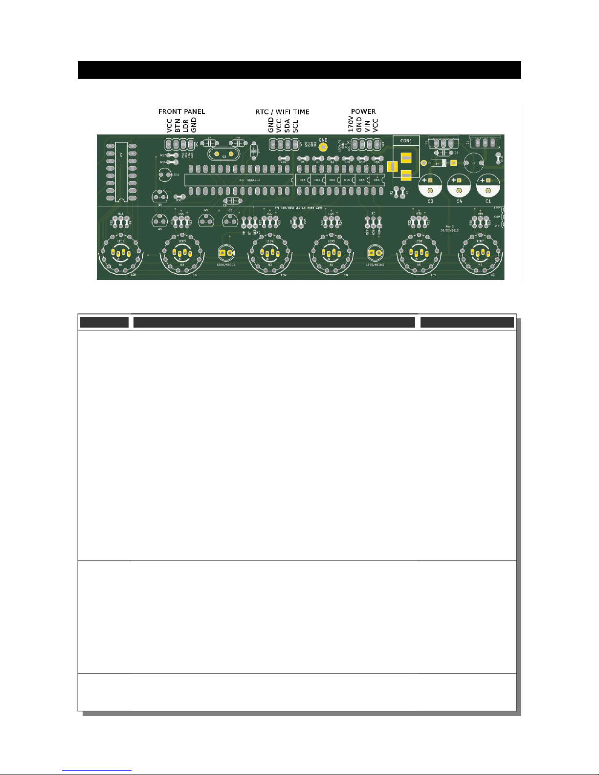
Board layout
For reference, the board layout is as shown (viewed fro the top):
The connections are:
Connector Description Values
POWER External power should be applied to the board with this connector.
Any DC input source is possible, fro 7.5V – 12V. Higher voltages
ay be possible, but could cause the digits to flicker if the voltage is
too high, and you ight have to provide a heat sink for the the
MOSFET and voltage regulator.
The absolute axi u input voltage is 24V. Any higher voltage
than this will da age the board within a few seconds!
The input VIN is protected against the input being connected
reversed.
The input current ranges fro 300 A to 1A depending on the size
of the tubes and the nu ber of LEDs you are driving.
170V: Output of high voltage for driving external neons etc.
GND: The negative side of the input supply
VIN: The positive side of the input supply
VCC: Output of regulated 5V, which can be used to drive auxiliary
circuitry.
FRONT These are the controls that go on the front panel: The input button
and the Light Dependent Resistor to detect a bient light.
GND: The “ground”. One lead of the button and one lead of the LDR
and one lead of the button are connected to this.
BTN1: The other lead of the button is connected to this input
DLS: “Di ing LDR Sense”: The other lead of the LDR is connected
to this
VCC: Regulated 5V output to drive any LEDs or lighting. Note that
you can also connect the LEDs to the VIN if you want to reduce the
load of the regulator.
RTC / WIFI The connection for the RTC (Real Ti e Clock) or WiFi ti e provider
odule. Connect this to the appropriately arked ter inals on the
RTC / WIFI odule.
Table des matières
Autres manuels Arduino Horloge


Manuels Horloge populaires d'autres marques

Silicon Laboratories
Silicon Laboratories SI5324 Manuel utilisateur

Heathkit
Heathkit GC-1005 Manuel utilisateur

Oregon Scientific
Oregon Scientific PRYSMA RMR221P Manuel utilisateur

Andrew O'Malley
Andrew O'Malley DOTKLOK Manuel utilisateur

ALGE-Timing
ALGE-Timing ASC3 Manuel utilisateur

Bodet
Bodet Profil 960 Manuel utilisateur


