Aquacom MK-IV Manuel utilisateur

MK-IV
3-Diver Intercom
“Technology in Depth”
Full-Duplex Surface Station
for Underwater Communications
Aquacom®

i
- NOTICE -
This manual and the information contained herein are provided for use as a main-
tenance and operation guide. No license or rights to manufacture, produce, and/
or sell either the manual or articles described herein are given. Undersea Systems
International, Inc., dba Ocean Technology Systems hereinafter referred to as OTS,
reserves the right to change specications without notice. It is recommended that
all users read and fully understand this manual before using the MK-IV 3-Diver
Intercom.
All statements, technical information, and recommendations herein are based on
tests we believe to be reliable, but the accuracy or completeness thereof is not guar-
anteed; and the following is made in lieu of all warranties, expressed or implied,
including the implied warranties of merchantability and tness for purpose: Seller’s
and Manufacturer’s only obligation shall be to replace such quantity of the product
proved to be defective. Before using, the user shall determine the suitability of the
product for intended use, and the user assumes all risk and liability whatsoever in
connection therewith. Neither Seller nor Manufacturer shall be liable either in tort
or in contract for any loss or damage—direct, incidental, or consequential—arising
from the use of or the inability to use the product. No statement or recommenda-
tion not contained herein shall have any force or effect unless it is in an agreement
signed by ofcers of the Seller and Manufacturer.
- IMPORTANT SAFETY NOTICE -
(Please read before using product.)
It is absolutely essential that all operators are properly trained and equipped
and fully understand this user’s manual before attempting to use the MK-IV
3-Diver Intercom.
While the MK-IV provides good underwater communications, it does not
change or eliminate the potential hazards of diving!
506118-000 (J)
Copyright © 2010 by Undersea Systems International, Inc., dba
Ocean Technology Systems. All rights reserved.
Specications are subject to change without prior notice.
Refer to the Library page of our Web site, www.otscomm.com, for a list of
any changes made to this manual since its publication.
Undersea Systems International, Inc.
dba
Ocean Technology Systems

TABLE OF CONTENTS
Section 1: Introduction ...............................................................................1
1.1 General.........................................................................................1
1.2 Specications ...............................................................................2
Section 2: Equipment Description .............................................................3
2.1 Package Design............................................................................3
2.2 Included with the MK-IV.............................................................3
2.3 Additional Components, Sold Separately....................................3
2.3.1 Communication Cables ................................................. 3
2.3.1.1 ComRopes ...................................................3
2.3.1.2 Spiral Four ...................................................4
2.3.1.3 Shielded Cable.............................................5
2.3.2 Diver Microphones........................................................5
2.3.2.1 ME-16R Hot-Mic®(912086-000)................ 5
2.3.2.2 Super Mic®Depth Master............................ 5
2.3.2.3 Preamplied, Powered Microphones...........6
2.3.3 Earphone-Microphone (EM) Assemblies ......................6
2.3.3.1 EMA-2 (911060-001) ..................................6
2.3.3.2 EMA-2SM (911060-098) ............................6
2.3.3.3 EMX-2 (911060-008) ..................................6
2.3.3.4 EMX-2B (911060-026) ...............................6
2.3.3.5 EMO-2 (900096-686)..................................6
2.3.3.6 EMH2-1 (911060-009) ................................6
2.3.3.7 EMH2-1SM (911060-100) ..........................7
2.3.3.8 EMS-2 (911060-017)...................................7
2.3.3.9 LAR V Adapter (900282-000).....................7
2.3.3.10 EMD-2 (911060-067) ..................................7
2.3.3.11 EMD-2SM (911060-101) ............................7
2.3.3.12 EMDG-2 (911060-076) ...............................8
2.3.3.13 EMH1-1 (900332-000)................................8
2.3.3.14 EMH1-1SM (900332-001) ..........................8
2.3.3.15 EMMT-1 (911060-090) ...............................8
2.3.3.16 EMMT-1SM (911060-102)..........................8
2.3.3.17 EMMT-2 (911060-091) ...............................8
2.3.3.18 EMMT-2SM (911060-103)..........................8
2.3.4 HHM-IV Hand-Held Microphone .................................8
2.3.5 Umbilical Adapters........................................................8
2.4 Functions......................................................................................8
Section 3: Supplying Electrical Power .................................................... 11
3.1 Battery Power............................................................................. 11
ii

iii
3.1.1 Battery Charging.......................................................... 11
3.1.2 Battery Replacement ................................................... 12
3.2 AC Power...................................................................................13
3.2.1 Electrical Safety Mechanisms .....................................14
3.2.1.1 GFCI ..........................................................14
3.2.1.2 Thermal Breaker........................................15
3.3 External DC Power ....................................................................15
Section 4: Operation .................................................................................16
4.1 Adjustments and Controls..........................................................16
4.1.1 System Power ..............................................................16
4.1.2 Diver Controls .............................................................16
4.1.2.1 Diver Audio Volume Controls ...................16
4.1.2.2 INAC Control ............................................16
4.1.2.3 Microphone Type Selection.......................17
4.1.2.4 Diver PTT Control..................................... 18
4.1.3 Tender Control.............................................................18
4.1.4 Speaker Power and Volume.........................................19
4.2 Setup ..........................................................................................19
4.3 Reception ...................................................................................21
4.4 Transmission ..............................................................................22
4.5 Recording Communications.......................................................22
4.6 After the Dive ............................................................................22
4.7 Helpful Hints..............................................................................22
Section 5: Maintenance and Troubleshooting ........................................24
5.1 Preventive Maintenance.............................................................24
5.2 Troubleshooting .........................................................................24
Appendix: Spare Components and Parts ...............................................27
Limited Warranty .....................................................................................28
Tables
Table 1: Compatible EM Assemblies with Standard Microphones ........7
Table 2: Battery Voltage Indication ...................................................... 11
Table 3: Connectors and Wiring of External Devices...........................20
Table 4: Troubleshooting ................................................................25–26
Illustrations
Figure 1. Examples of Standard and Preamplied Microphones ...........4
Figure 2. MK-IV Panel Layout...............................................................9
Figure 3. Battery Panel Assembly ........................................................13
Figure 4. Electrical Safety Mechanisms ...............................................14
Figure 5. Location of Microphone Type Selection Switch...................17

SECTION 1
INTRODUCTION
Congratulations! You have just purchased one of the nest, state-of-the-art under-
water communication systems available. The Aquacom®MK-IV 3-Diver Intercom
allows open “round robin” communications through intercom lines among a surface
tender with a headset (included) and up to three divers with earphone-microphone
assemblies (sold separately). All users can speak and listen simultaneously, without
the need for a push-to-talk system that would interrupt communications.
The MK-IV 3-Diver Intercom represents the latest generation of intercom technol-
ogy with many useful features for outstanding performance, including an INAC
(Inhalation Noise Attenuation Circuit) for reduction of diver inhalation noise; a
MIL-spec speaker designed for high-quality sound; MIL-spec connectors for all
communication connections; capability of both powered (preamplied) and non-
powered microphones; remote speaker and record-out connections; GFCI and
transformer isolation for enhanced diver safety; a durable, heavy-duty housing;
and much more. In all, the MK-IV 3-Diver Intercom is second to none!
1.1 GENERAL
This manual contains much of the information you will need to know regarding the
Aquacom®MK-IV 3-Diver Intercom communication system. Section 1 contains a
table of specications and an overview of the functions of the MK-IV.
Before operating the MK-IV 3-Diver Intercom, read this entire manual. In addition
to the information presented on functions and operation, there are some important
safety issues all users must be familiar with before using the MK-IV. If you have
any questions, contact your local OTS dealer, or feel free to contact OTS directly
(see page 28 for OTS contact information).
1

2
1.2 SPECIFICATIONS
Input voltage: 90–264 V AC, 47–63 Hz
Input current: 5 amps DC
Idle current: 125 mA
Audio power: 16 watts max (4 watts per diver, 2 watts each
for tender headset and speaker)
Frequency response: 300–4000 Hz
Microphone input impedance: (Non-powered) 150 ohms
Headphone impedance output: 300 ohms
Protection circuits: GFCI: 10 mA through ground path
Thermal circuit breaker: 2 A slow trip
Battery type: Rechargeable, lead acid, 12 V, 5 Ah
Battery life: 14 hours continuous use (full charge)
Operating temperature: -40°C to 50°C (-40°F to 122°F)
(not charging batteries; not mains power)
-40°C to 40°C (-40°F to 104°F)
(w/ mains power and charging)
Note: Room temperature recommended for
charging.
Storage temperature: –25°C to 65°C (–13°F to 149°F)
Cabinet material: Molded composite
Front-panel material: 0.080” stainless steel, powder coated
Housing dimensions: Height: Lid on: 14-1/2 inches
Lid off: 8-1/2 inches
Width: 14 inches
Depth: 12-1/2 inches
Weight: 28 lbs.

SECTION 2
EQUIPMENT DESCRIPTION
2.1 PACKAGE DESIGN
The Aquacom®MK-IV 3-Diver Intercom is housed in a sturdy, impact- and rust-
resistant berglass case with stainless steel latches. The case is opened with a
counterclockwise rotation of the handles on the two buttery latches that secure
the lid; the lid can be fully opened and even removed easily at the hinge. The
conguration of the multiple sets of feet on the case allows the unit to stand safely
with the panel facing upward or forward.
The connectors and control knobs on the front panel are all military style and are
therefore constructed to a high quality standard, providing ruggedness and durabil-
ity for use in marine and other harsh environments.
The panel speaker meets military standard MIL-L-24296A and is built for durability
and endurance under demanding environmental conditions. Its resistance to shock,
vibration, and salt spray make it an excellent speaker for oceanic shipboard use.
2.2 INCLUDED WITH THE MK-IV
The following items are provided with the MK-IV:
• THB-16 tender headset with boom microphone (part no. 900298-032)
• AC power/charging cable (part no. 914081-000)
• Two (2) four-socket military-style (MS) connectors (OTS part no. 211106-000;
industry part no. MS3116F8-4S)
• MK-IV 3-Diver Intercom user’s manual (document no. 506118-000)
• Warranty card with the MK-IV unit’s serial number (doc. no. 506014-000)
2.3 ADDITIONAL COMPONENTS, SOLD SEPARATELY
2.3.1 COMMUNICATION CABLES: Each diver requires an intercom cable
for connection from his earphone and microphone to the MK-IV. Be sure to obtain
the 5-pin military-style plug on one end that matches the diver umbilical receptacles
(Section 2.4, Item 5) on the MK-IV (refer to Table 3, Item 1 in Section 4.2). The
other end of the cable should have the connector for your particular earphone-
microphone assembly.
2.3.1.1 ComRopes: OTS offers ComRopes consisting of communication cables
bundled inside a durable yet exible rope. Various lengths of ComRopes are avail-
able with connectors to match different earphone-microphone assemblies. Contact
OTS or your local OTS dealer for information about available ComRopes for use
with the MK-IV.
3

2.3.1.2 Spiral Four: This cable has been used extensively with military and
commercial divers for many years. It has been available as military surplus but is
becoming harder to nd. However, there are some cable manufacturers that have
duplicated this cable, and it is now available to the diving community.
The most important feature of this cable is the internal wires used for microphone
and earphone circuits. Usually, there are two white and two brown or black cables,
congured in a twisted pattern. Always connect the speaker or microphone to either
the white pair or the black (brown) pair. If this is not done, electrical feedback
(squeal) will occur. When connected correctly, the cable is balanced, and clear
communication is possible.
4
Figure 1. Examples of Standard and Preamplied Microphones
(A) Non-powered, dynamic mic (ME-
16R Hot-Mic® for Interspiro
FFM)
(B) Non-powered, dynamic mic
(Shure microphone for band
mask or SuperLite®helmet)
(D) Powered (preamplied) micro-
phone for band mask or Super-
Lite®helmet)
(C) Powered (preamplied) micro-
phone for Interspiro FFM

2.3.1.3 Shielded Cable: Another available cable contains at least one twisted,
shielded balanced cable and a second twisted, shielded or unshielded pair. The
unshielded pair is used for the earphones, while the balanced, twisted pair is used
for the microphone. Unlike spiral four cable, little can go wrong with this system,
provided the microphone is connected to the shielded, twisted, balanced cable.
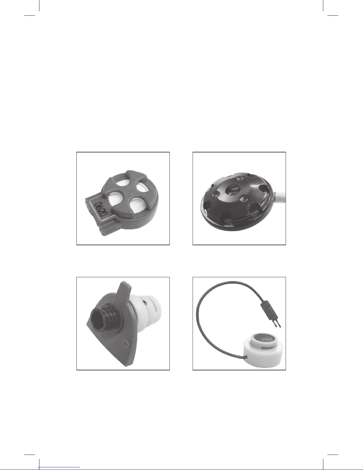
2.3.2 DIVER MICROPHONES
See Figure 1 for examples of non-powered and powered (preamplied) micro-
phones.
2.3.2.1 ME-16R Hot-Mic
®
(912086-000): The ME-16R Hot-Mic
®
(Fig. 1A) is
a 150-ohm, water-resistant microphone element. It is a state-of-the art dynamic
microphone element designed to give you long, trouble-free use and the highest
intelligibility possible.
Although the Hot-Mic is trouble free, it should be maintained. Rinse it with
freshwater after use to get all dirt, debris, or salt water from the grill. Dry it with a
clean, soft towel. If the element ever needs to be replaced, it is easily removed by
unscrewing the two small screws located on its base.
Getting the microphone wet does not harm it. However, the microphone element
can only withstand an 8- to 10-foot depth/pressure differential. If you removed your
diving FFM at the back of the boat and the microphone became wet, there would
be no problem; but if the FFM with element dropped more than 8 to 10 feet into the
water, the change in pressure probably would damage the microphone element. In
tests we have taken off the FFM at 30 feet and replaced it, still at 30 feet, without
any problem; but if one were to take off the FFM at 30 feet and drop down to 40
feet, the pressure difference may damage the microphone.
2.3.2.2 Super Mic
®
Depth Master: The Super Mic
®
offers patented technol-
ogy* that overcomes a limitation of other microphones. It can be used at any depth
and—unlike the Hot-Mic or many other microphones—can withstand changes in
depth while submerged, so it will not be damaged if the diver needs to descend
with the mask ooded (such as when a full-face mask is removed and stowed
when the diver changes to another air system). It is a ceramic microphone with a
compact, lightweight design and noise-cancelling properties, reducing background
noises for clearer communications. When only the highest quality of intelligibility
is required, the Hot-Mic is the preferred choice; but the Super Mic’s intelligibility
is sufcient for most diving situations.
To assure clear communications when using the Super Mic, it should be no more
than 1/4 inch from the corner of the diver’s mouth.
After each dive, clean the Super Mic by rinsing it with freshwater and drying it
with a clean, soft towel. No other maintenance is required.
5
*U.S. Patent no. 7,170,822; EU patent nos. 000458351-0001, -0002, -0003, -0004, -0005, -0006.

Note: Do not press on the microphone diaphragm; doing so may cause damage.
2.3.2.3 Powered, Preamplied Microphones: The MK-IV supports the use
of preamplied microphones (Fig. 1C & D), which tend to be more durable and
rugged and require less maintenance than standard microphones—although they
often have lower delity, with somewhat diminished dynamic range and speech
intelligibility. Powered microphones are available separately with two-contact
connectors or can be custom-tted with earphones, depending on your particular
requirements. For information on available powered microphones, contact OTS
or your local OTS dealer.
2.3.3 EARPHONE-MICROPHONE (EM) ASSEMBLIES: We offer our
standard microphones integrated into earphone-microphone (EM) assemblies
designed to t the communication port of full-face masks (FFMs) produced by
various manufacturers. Table 1 is a compatibility chart of some of the standard
(non-powered) EM assemblies available for use with a ComRope connected to the
MK-IV 3-Diver Intercom. Note: If you have a diving helmet or mask that is not on
the compatibility chart, contact OTS or your local OTS dealer for availability or
for information on custom EM assemblies.
The following are full descriptions of each of the EM assemblies listed in Table
1:
2.3.3.1 EMA-2 (911060-001): The EMA-2 EM assembly is designed for all
Divator MKII (“AGA”) full-face masks (FFMs). It has two ceramic earphones with
holders, an ME-16R Hot-Mic, a Hi-Use®connector, and a push-to-talk (PTT) but-
ton. The assembly is installed into the Divator MKII FFM communication port.
2.3.3.2 EMA-2SM (911060-098): The EMA-2SM EM assembly is designed
to be installed into all Divator MKII (“AGA”) FFMs. It consists of two ceramic
earphones with holders, a Super Mic, a Hi-Use®connector, and a PTT button. The
assembly is installed into the Divator MKII FFM communication port.
2.3.3.3 EMX-2 (911060-008): The EMX-2 EM assembly is designed for the
EXO-26 original FFM. It consists of two dynamic earphones, an ME-16R Hot-
Mic, a Hi-Use®connector, and a PTT button.
2.3.3.4 EMX-2B (911060-026): The EMX-2B EM assembly is designed for the
EXO-26 standard full-face mask. It is similar to the EMX-2 but ts the balanced-
regulator version of the EXO-26 with an oral-nasal cavity.
2.3.3.5 EMO-2 (900096-686): The EMO-2 EM assembly is designed to be in-
stalled into the Ocean Reef NIRA Neptune FFM. It has two earphones with holders,
a Hot-Mic, a Hi-Use®connector, and a PTT button. It is installed into a port on the
side of the FFM.
2.3.3.6 EMH2-1 (911060-009): The EMH-1 EM assembly is optionally included
with the HM-2 mouth mask. It has one head strap, one ceramic earphone, a Hot-
6
Table des matières
Autres manuels Aquacom Système d'interphone


