
Aqua Creek F-700RL Manuel utilisateur

Copyright © 2016 Aqua Creek Products All Rights Reserved Revised 8/11/16
Revolution Lift
Manual
9889 Garrymore Ln | Missoula, MT 59808
888-687-3552 | +1-406-549-0769
www.aquacreek.com
PART #: F-700RL (with anchor)
PART #: F-702RLNA (without anchor)
US PATENT NUMBER: [D507,769 S]
500 LB. [227 kg] MAXIMUM WEIGHT CAPACITY
MANDATORY
LEAVE THIS MANUAL WITH LIFT OWNER
Read and follow all instructions.
Lift safety can only be ensured if installed and operated
according to these instructions.
• NEVER permit children to play on or around the lift
• Do not allow children to use the lift without adult
supervision
• NEVER apply direct water pressure to the electronics
• NEVER use the lift with a dry pool
Check entire box and all packing materials for parts. Before beginning assembly, read the
instructionsandidentifypartsusingtheguresandpartslistedinthisdocument.
It is critical that all parts be carefully inspected prior to installation. If any damage occurred in
transit,AquaCreekProducts,LLCmustbenotiedwithinthreedaysofreceiptofunit.
Proper installation cannot be overstressed, as an improper installation voids Aqua Creek’s
warranty and may affect the safety of the user.
READ CAREFULLY
ADA COMPLIANT
1

Copyright © 2016 Aqua Creek Products All Rights Reserved Revised 8/11/16
1
2
3
4
5
6
8
7
Revolution Lift
Revolution Components
Table of Contents
PAGE DESCRIPTION PAGE DESCRIPTION
2 Revolution Components 10 Battery Maintenance
3 ADA Installation Guidelines 11 Revolution Parts List
4 Anchor Installation: New Construction 12 Chair & Footrest Parts List
5 ADA Fixing Insert Installation 13 Warranty
6-8 Revolution Assembly Instructions
9 Troubleshooting Guide
10 Care For Your Lift
1. The Revolution Main Assembly
2. Control Arm
3. Lifting Arm
4. Seat Arm
5. Footrest
6. Actuator
7. Handset
8. 24V Battery
2
Copyright © 2016 Aqua Creek Products All Rights Reserved Revised 8/11/16
Installation: ADA Guidelines
16"
MIN.
[40.6 cm]
48"
[122 cm]
36"
[91.4 cm]
29"
[73.7 cm]
[172.5cm]
68"
[30.5cm]
12"
ADA
REQUIRED
CLEAR DECK
SPACE
DECK
WATER
POOL WALL
FIGURE 1
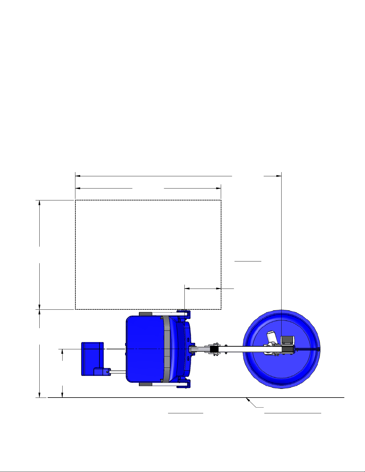
ADA Requirements:
The Revolution Lift is ADA Compliant.
The installation must meet the following requirements:
• Clear deck space dimensions (see FIGURE 1)
• Installed a minimum of 16 inches from the pool wall
• Deck slope no greater than 1:48
• The seat must submerge at least 18 inches into the water. The lift should be installed at a location with
42inches-48inchesofdepth(decktopooloor)
• Anchor setbacks are based on straight pool/spa walls. Curved pool/spa walls will effect the anchor setback.
3

Copyright © 2016 Aqua Creek Products All Rights Reserved Revised 8/11/16
Anchor Installation: New Construction or Retro-Fit
You may need to saw cut and remove a portion of an existing pool deck in order to achieve the 10 inch depth
footing requirement. Aqua Creek does NOT recommend a core drill installation for this lift.
To properly install this anchor, you will need to have a concrete footing comprised of 4500 psi concrete that is
10 inches deep and 4 feet - 3 inches square and reinforced with rebar. Refer to Figures A and B below.
If cutting into an existing pool deck, the rebar must be drilled and secured to the surrounding pool deck on
three sides (do not secure into bond beam). The centerline of the anchor should be no less than 9 inches from
the edge of the footing.
NOTE: The anchor setback will vary depending on application and any options you choose for the lift. 16
inch setback is the minimum for ADA compliance however, given a typical 1 foot bond beam and the fact that
the anchor should be no closer than 9 inches to the edge of your footing, 21 inches may be the closest you
can achieve. The chart below outlines the minimum and maximum anchor setback locations for the available
options based on this premise. Also, some attachments will de-rate the lifting capacity of the lift. Refer to the
attachment manual or spec sheet to check for changes in lifting capacites.
1. Determine the location for the anchor based on the options you are ordering or think you may order in the
future and set the anchor in place. You may use a small mass of wet concrete to set the anchor in place.
Usealevelandstringlinestomakesuretheanchorisperpendicularandwillbeushwiththetopofthe
nisheddecksurface.
2. Bond the anchor according to local code requirements using the bonding lug on the bottom of the anchor.
ReferencetheNationalElectricCode(NEC)Article680.26forspecicsonbonding.
3. PourtheconcretesothatthetopoftheanchorwillbeushwiththeFINISHEDpooldecksurface.
4. Once the concrete has cured, the lift can be put into place.
ITEM NO. OPTION MIN MAX
F-730RSA-S2 GURNEY 21” 32”
F-706RLSS SLING SEAT 21” 24”
F-734RSA SPINE BOARD 21” 34”
F-705-S2 WHEELCHAIR ADAPTER 21” 34”
4'-3"
2'-1
1
2
"
9"
MIN
1'-0"
MIN.
1'-9" MIN.
3'-0" MAX.
4'-3"
4'-3"
3"
CLR
81
2
"
10"
2"
CLR
EPOXY TOP MATT
TO EXISTING SLAB
(4" MIN. EMBED)
REVOLUTION
BRONZE ANCHOR
SLEEVE
4'-3" SQ. x 10" DEEP
CONC. FTG. W/4 - #5
E.W., TOP & BTM. &
#4 U BAR @ TOP
(SEE FIGURE B)
DECK
POOL
WALL
FIXING
ANCHOR
FIXING
ANCHOR
LOCKING-PIN
SLOT
2'-0"
2'-0"
1'-0"
FIGURE A
FIGURE B
4

Copyright © 2016 Aqua Creek Products All Rights Reserved Revised 8/11/16
ADA Fixing Insert Installation (Commercial Applications)
1. Duetotheindexedanchorandkeyedbaseofthelift,werecommendinstallationofthexinginsertafter
the concrete has cured and you are ready to install the lift into the anchor.
2. Place the main assembly in the anchor and turn until the locking pin on the shaft of the lift lines up and
drops into the locking pin slot in the anchor. DO NOT LIFT THE MAIN ASSEMBLY BY USING THE ELECTRIC
RAM AS A HANDLE. If the transport cart was ordered with the lift, it can be used effectively here. If not,
use two people.
3. Markthelocationforthexinganchorholeandremovethelift. (see pg 4, FIGURE A)
4. Drill the hole with a 1 1/4 inch core drill or roto-hammer to a depth of about 4 1/2 inches.
5. Cleantheholeoutandmakesureitisdry.Threadthe1/2inchboltintothetopofthePVCxinganchor
andtestttoverifyitcanbemountedperpendicular.SeeStep1below.
6. Usingatwopartconstructionepoxy,lltheholeapproximatelyhalffullandcarefullyinsertthePVCxing
anchor into the hole, twisting as you push down to evenly spread the epoxy.
7. Allow the epoxy to cure before securing the lift.
8. Re-install the lift into the anchor and using the 1/2 inch bolt and washer, carefully thread into the installed
anchor until snug. TO PREVENT BREAKING THE FIXING BRACKET, DO NOT OVERTIGHTEN!
POST
ANCHOR
DECK
MAIN ASSEMBLY
LOCKING PIN
LOCKING SLOT
1/2" X 2"
HEX BOLT
1/2" FLAT
WASHER
STEP 1
5

Copyright © 2016 Aqua Creek Products All Rights Reserved Revised 8/11/16
1/2" X 2-3/4"
SHOULDER
BOLT
3/8" FLAT
WASHER
3/8" NYLOCK
NUT
MAIN
ASSEMBLY
CONTROL
ARM
AA
B
B
Revolution Assembly Instructions
STEP 2: INSTALL LIFTING ARM
Locate the LIFTING ARM and the following hardware:
• (1) 1/2” x 2-3/4” SHOULDER BOLT
• (1) 3/8” x 2” SHOULDER BOLT
• (1) 5/16” FLAT WASHER
• (1) 5/16” NYLOCK NUT
• (1) 3/8” FLAT WASHER
• (1) 3/8” NYLOCK NUT
Remove the shipping strap and all packing from
the LINEAR ACTUATOR. Connect the LIFTING ARM
between the MAST and the LINEAR ACTUATOR as
showninthegurebelow.Makesuretheendmarked
“B” attaches to the mast. Tighten NYLOCK NUTS (2)
until snug as shown in PHOTO 2.
DO NOT OVERTIGHTEN!
STEP 3: INSTALL CONTROL ARM
Locate the CONTROL ARM and the following
hardware:
• (1) 1/2” x 2-3/4” SHOULDER BOLT
• (1) 3/8” FLAT WASHER
• (1) 3/8” NYLOCK NUT
Install the CONTROL ARM (end marked “A”) onto
theMASTasshowninthegurebelow.Tightenthe
NYLOCK NUT until snug as shown in PHOTO 3. DO
NOT OVERTIGHTEN!
STEP 2 STEP 3
1/2" X 2-3/4"
SHOULDER
BOLT
3/8" FLAT WASHER
3/8" NYLOCK NUT
3/8" X 2"
SHOULDER
BOLT
5/16" FLAT
WASHER
5/16" NYLOCK
NUT
MAIN
ASSEMBLY
LINEAR
ACTUATOR
B
A
B
D
LIFTING ARM
6

Copyright © 2016 Aqua Creek Products All Rights Reserved Revised 8/11/16
Revolution Assembly Instructions
STEP 4: INSTALL SEAT ARM
Locate the SEAT ARM and the following hardware:
• (2) 1/2” x 3” SHOULDER BOLT
• (2) 3/8” FLAT WASHER
• (2) 3/8” NYLOCK NUT
Install the SEAT ARM at the ends of the CONTROL
ARMandLIFTINGARMasshownintheguretothe
left. Tighten the NYLOCK NUTS until snug as shown in
PHOTO 4. DO NOT OVERTIGHTEN!
(NOTE: MAKE SURE THE SEAT IS FACING AWAY FROM
THE MAIN ASSEMBLY)
NOTE: FOR APPLICATIONS THAT UTILIZE MULTIPLE
SEAT ARMS (SUCH AS FOR A SLING SEAT OR THE SPA
SEAT-ARM) USE THIS STEP TO REMOVE AND REPLACE
THE SEAT ARM.
STEP 5: ADJUST THE SEAT POSITION
The SEAT ASSEMBLY will arrive attached to the SEAT ARM
adjusted to its highest position. To adjust the SEAT ASSEMBLY
to a lower position remove the hardware as shown below.
Slide the SEAT ASSEMBLY to its desired position (in 4 inch
increments) and reinstall the hardware. The maximum
adjustment is 16 inch (down).
DO NOT ATTACH THE SEAT ASSEMBLY ANY LOWER THAN THIS
– ALWAYS USE THE TWO (2) SUPPLIED BOLTS TO ATTACH THE
SEAT ASSEMBLY TO THE CHAIR ARM!
NOTE:Formostapplications,suchaspoolswithaatdeck,
the seat will be installed in its lowest position. For applications
where a wall or curb must be cleared the seat should be
installed in a higher position. In its highest position the seat
will clear a 30 inch [762mm] high wall.
1/2" X 3"
SHOULDER
BOLT
3/8"
NYLOCK
NUT
3/8"
FLAT
WASHER
CONTROL
ARM
LIFTING
ARM
*NOTE: FOR APPLICATIONS WHICH USE
MULTIPLE SEAT-ARMS, REMOVE NUTS &
BOLTS AND REPLACE ARM AS REQUIRED.
*STANDARD SEAT-ARM
(OR SPA SEAT-ARM,
OR SLING SEAT-ARM)
STEP 4
SEAT-ARM
HOLES AT 4"
INTERVALS
ALLOW FOR
ADJUSTMENT
OVER 16"
RANGE
SEAT ASSEMBLY
ADJUSTED TO
LOWEST POSITION
(SEAT WILL ARRIVE
AT HIGHEST
POSITION)
MAIN
ASSEMBLY
5/16" X 4-3/4"
HEX BOLT
5/16" FLAT
WASHER
5/16" NYLOCK
NUT
5/16" FLAT
WASHER
3/8" X 2"
SHOULDER BOLT
STEP 5
7

Copyright © 2016 Aqua Creek Products All Rights Reserved Revised 8/11/16
QUICK
RELEASE
PIN
FOOTREST
TUBE
(ADJUSTABLE)
SEAT
ASSEMBLY
24V
BATTERY
CONTROL
BOX
HANDSET
CONTROL
Revolution Assembly Instructions
STEP 6: INSTALL THE FOOTREST
Locate the FOOTREST ASSEMBLY and install it on
the seat as shown below. The QUICK RELEASE PIN is
attached to the SEAT ASSEMBLY with a lanyard (cable).
Pull out the pin and slide the FOOTREST ASSEMBLY
into the slot and line up one of the holes on the
FOOTREST TUBE with the hole for the pin. Push the
pin back into the hole and through the hole in the
FOOTREST TUBE to hold the FOOTREST ASSEMBLY
in the desired position. To re-adjust the FOOTREST
simply pull out the pin and select a new hole on the
FOOTREST TUBE.
STEP 7: INSTALL 24V BATTERY & HANDSET
Locate the 24V battery, the battery charging unit
and the handset control. Charge the battery for 24
hours then install it on the bracket above the control
box as shown on PHOTO 7. Plug the handset control
intothecontrolboxasshowninthegureandin
thephotosbelow.Pressrmlytomakesuretheplug
is fully seated as shown below.
THE LIFT WILL NOT FUNCTION IF THE HANDSET
PLUG IS NOT FULLY SEATED OR IF THE BATTERY IS
NOT PROPERLY ALIGNED.
STEP 6
STEP 7
SeatedNot Seated
8

Copyright © 2016 Aqua Creek Products All Rights Reserved Revised 8/11/16
Basic Troubleshooting
Problem: The lift won’t move.
Solution:
1. Make sure the battery is properly seated:
You should hear a click when
the battery is properly seated
on the control box or charger.
Click!
NOT Properly Attached:
Note: the white bracket is
in front of the silver clip,
which will not allow for
an electrical connection
Properly Attached:
Note: the white bracket
is behind the silver clip,
holding it securely to
allow for an electrical
connection
Check the ends of the cords for corrosion or
damage. The cord plugs should be recessed
into the outlet. You should feel them pop into
place when they are correctly inserted.
2. Make sure the cords are properly plugged in:
NOT Properly Inserted:
The cord plug is fl ush with
or sticking out of the outlet
Properly Inserted:
The cord plug is recessed
into the outlet
POP!
The Charger is ON
when the green
light is glowing
The Battery is
CHARGING when the
orange light is glowing
When the Battery is
charged the orange
light will stop glowing
4. Make sure the battery is fully charged:
3. Check the contact points:
Make sure the contact points of
the control box and the battery
are not damaged or corroded.
If there is corrosion clean with
Scotch-BriteTM pad. Put some
dielectric grease on the contact
points before reattaching the
battery.
Problem: The lift stopped moving over the water and is stuck.
Solution:
1. Press the emergency button
Use a pen or pencil tip and stick it into
the emergency button on the front of the
control box to retract the lift.
Note: the lift will not retract if the battery
is not fully charged or if the control box is
not working. The emergency button only
overrides the remote handset. 9

Copyright © 2016 Aqua Creek Products All Rights Reserved Revised 8/11/16
Proper Care of Pool & Spa Lifts
PROCEDURE DAILY WEEKLY MONTHLY
Wash down lift with fresh water and dry with clean, soft,
non-abrasive cloth.
Recharge battery.
Run the lift through a complete test cycle to verify it is
functioning properly.
Visually inspect lift for damage, corrosion, and loose or
missing hardware.
Check all contact points for damage and/or corrosion.
Repair, clean, and apply dielectric grease to all contact
points.
Thoroughly clean lift frame and apply a liberal coat of car
wax to maintain the lift’s nish.
Check all Warning and Cautionary labels to make sure they
are not faded or worn. Replace as needed.
PROPER CARE NOTES
• Use only fresh water to wash your lift. Do not wash with pool water.
• Use only clean, soft, non-abrasive cloths to wipe down your lift.
• Do not store lift in pump room or near chemicals.
• Do not allow children to play on or around this lift.
• When cleaning the lift, do not spray water directly on control box or battery.
• The lift may need to be bonded according to local code requirements.
For service and/or replacement parts contact Aqua Creek direct at
Toll free: (888) 687-3552
To remove stubborn stains from nish, spray aected area with Mild Dish Soap, rub
briskly with a 3M Scotch Brite™ pad. Use white epoxy paint to touch up the nish. Apply
wax to protect when dry.
STAIN REMOVAL TIPS:
10
Ce manuel convient aux modèles suivants
2
Table des matières
Autres manuels Aqua Creek Aide à la mobilité


Manuels Aide à la mobilité populaires d'autres marques


Rhythm Healthcare
Rhythm Healthcare B3800F Manuel utilisateur
AMF-BRUNS
AMF-BRUNS PROTEKTOR Manuel utilisateur

Drive DeVilbiss Healthcare
Drive DeVilbiss Healthcare OTTER Manuel utilisateur

Rhythm Healthcare
Rhythm Healthcare C500U Manuel utilisateur

Lumex
Lumex RJ4200A Manuel utilisateur

Rebotec
Rebotec Jumbo Manuel utilisateur