APS YC500-A Mode d’emploi

Installation/User Manual
APS YC500-A
Photovoltaic Grid-connected Inverter
Version 4.1 7/14
APS America
1015 Hostmark St. Ste 104; Poulsbo, WA 98370
WEB: www.APSamerica.com
© All Rights Reserved

TABLE OF CONTENTS
IMPORTANT SAFETY INSTRUCTIONS 1
Radio interference statement 2
APS Microinverter System Introduction 3
APS Microinverter 500 series Introduction 5
APS Microinverter System Installation 6
Additional Installation components from APS 6
Required Parts and Tools from installer 6
Installation Procedures 7
Step 1 - Installing the AC Branch Circuit Junction Box 7
Step 2 – Attaching the APS Microinverters to the Racking
or the PV Module Frame 8
Step 3 - Connecting the APS Microinverter to the PV Module 9
Step 4 - Ground the System 10
Step 5 –Connecting APS Microinverters to the AC Cables 11
Step 6 - Completing the APS Installation Map 12
APS Microinverter system operating instructions 13
Troubleshooting 14
• Status Indications and Error Reporting 14
• Operation LED 14
• GFDI Error 14
• Other Faults 14
Troubleshooting a non-operating APS Microinverter 15-16
Replace a Microinverter 17
Technical Data 18-19
Efficency Cruves 20
Wiring Diagrams 21
• Sample Wiring Diagram – 120V/240V Split Phase 22
• Sample Wiring Diagram – 120V/ 208V Three Phase 23
• Sample Wiring Diagram – 277V/480V Three Phase 23
iii
APS YC500-MIW Installation/User Manual

APS YC500-A Installation/User Manual 1
IMPORTANT SAFETY INSTRUCTIONS
SAVE THESE INSTRUCTIONS! This manual contains important
instructions to follow during installation and maintenance of the APS
Photovoltaic Grid-connected Inverter (Microinverter). To reduce the
risk of electrical shock and ensure the safe installation and operation
of the APS Microinverter, the following symbols appear throughout
this document to indicate dangerous conditions and important safety
instructions.
WARNING: This indicates a situation where failure to follow
instructions may cause a serious hardware failure or personnel danger
if not applied appropriately. Use extreme caution when performing
this task.
NOTE: This indicates information that is important for optimized
Microinverter operation. Follow these instructions closely.
SAFETY INSTRUCTIONS
✔Do NOT disconnect the PV module from the APS
Microinverter without rst disconnecting the AC power.
✔Only qualied professionals should install and/or replace APS
Microinverters.
✔Perform all electrical installations in accordance with local
electrical codes.
✔Before installing or using the APS Microinverter, please read all
instructions and cautionary markings in the technical documents
and on the APS Microinverter system and the PV-array.
✔Be aware that the body of the APS Microinverter is the heat sink
and can reach high temperatures. To reduce risk of burns, do not
touch the body of the Microinverter.
✔Do NOT attempt to repair the APS Microinverter. If it fails, contact
APS Customer Support (206-855-5100) to obtain an RMA number
and start the replacement process. Damaging or opening the APS
Microinverter will void the warranty.
1
WARNING
SYMBOL
NOTE
SYMBOL

APS YC500-A Installation/User Manual 2
RADIO INTERFERENCE STATEMENT
FCC Compliance: The equipment complies with the limits for a class
B digital device, pursuant to part 15 of the FCC Rules, which are
designed to protect against harmful interference in a residential
installation. The equipment could radiate radio frequency energy
and this might cause harmful interference to radio communications
if instructions were not followed when installing and using the
equipment. But there is no guarantee that interference will not
occur in a particular installation. If this equipment causes harmful
interference to radio or television reception, the following measures
might resolve the issues:
A) Relocate the receiving antenna and keep it well away from the
equipment
B) Consult the dealer or an experienced radio/TV technician for
assistance.
Changes or modications not expressly approved by the party
responsible for compliance may void the user’s authority to operate the
equipment.
Radio Interference Statement

APS YC500-A Installation/User Manual 3
APS YC500-A System Introduction
The APS Microinverter is used in utility-interactive grid-tied
applications, comprised of three key elements:
✹APS Microinverter
✹APS Energy Communication Unit (ECU)
✹APS Energy Monitor and Analysis (EMA) web-based
monitoring and analysis system
Figure 1

APS YC500-A Installation/User Manual 4
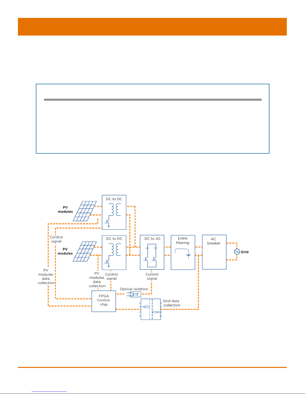
APS Microinverters maximize PV energy production
Each PV module has individual Maximum Peak Power Tracking
(MPPT) controls, which ensures that the maximum power is exported
to the utility grid regardless of the performance of the other PV
modules in the array. When PV modules in the array are affected
by shade, dust, orientation, or any situation in which one module
underperforms compared with the other units, the APS Microinverter
ensures top performance from the array by maximizing the
performance of each module within the array.
More reliable than centralized or string inverters
The distributed APS Microinverter system ensures that no
single point of system failure exists across the PV system. APS
Microinverters are designed to operate at full power at ambient
outdoor temperatures of up to 149°F (65°C). The inverter housing
is designed for outdoor installation and complies with the IP65
environmental enclosure rating.
Simple to install
You can install individual PV modules in any combination of module
quantity, orientation, type, and power rate.
Smart system performance monitoring and analysis.
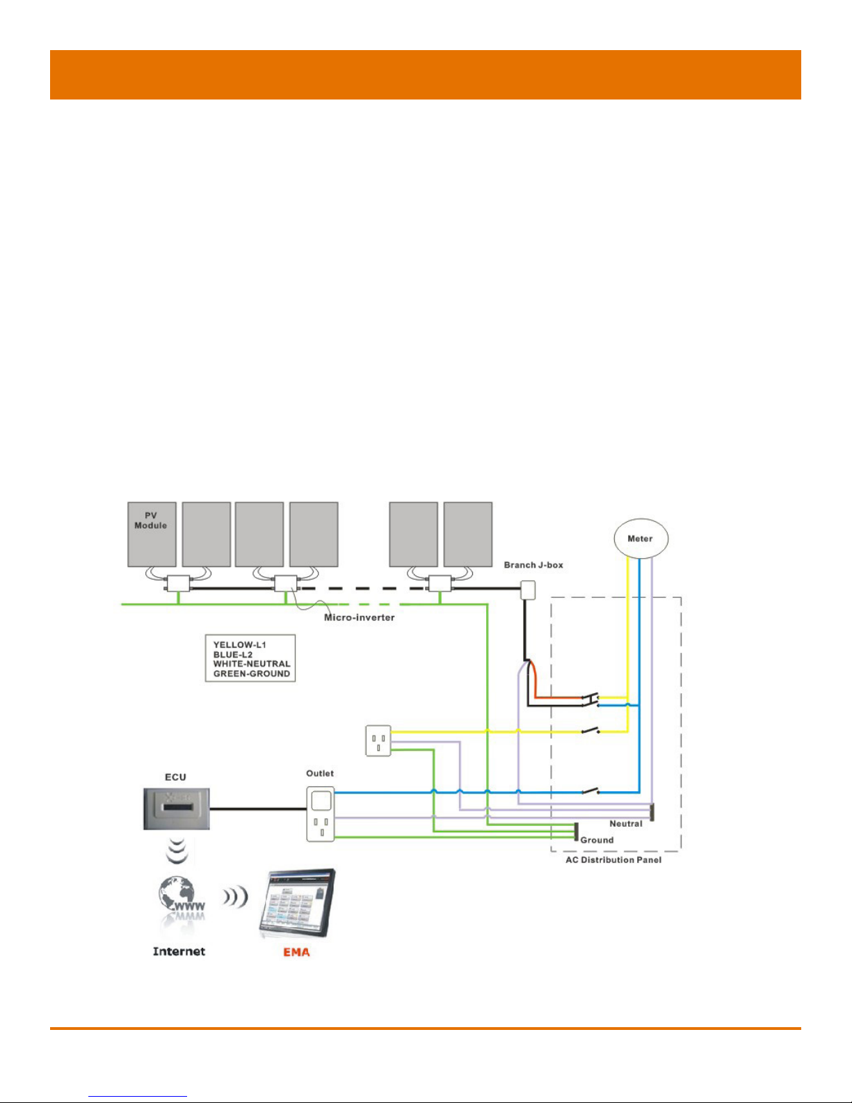
The APS Energy Communication Unit (ECU) is installed by simply
plugging it into any wall outlet and providing an Ethernet or Wi-
Fi connection to a broadband router or modem. After installing the
ECU, the full network of APS Microinverters automatically reports
to the APS Energy Monitor and Analysis (EMA) web server. The
EMA software displays performance trends, informs you of abnormal
events, and controls system shutdown when it is needed. (See ECU
manual for instructions.)

APS YC500-A Installation/User Manual 5 5
APS Microinverter 500 Series
The APS 500 series Microinverters connect with the Split-phase
grid, and operate with most 60 and 72 cell PV modules. For more
information, please see the Technical Data page (p.18) of this manual.
The APS YC500 has two independent DC inputs, each with
independent MPPT control and data monitoring.
The following gure shows the APS YC500 Microinverter schematic:
Figure 2
MODEL NUMBER AC GRID PV MODULE MODULE CONNECTOR
YC500 60Hz/240V 60,72 Cell MC-4 Type or Customize
Maximum units per branch of YC500
Max. parallel combination of APS modules = 7/branch for 20 A breaker (14 PV modules)

APS YC500-A Installation/User Manual 6
APS Microinverter System Installation
A PV system using APS Microinverters is simple to install. Each
Microinverter easily mounts on the PV racking, directly beneath the
PV module(s). Low voltage DC wires connect from the PV module
directly to the Microinverter, eliminating the risk of high DC voltage.
Installation MUST comply with local regulations and technical rules.
WARNING: Perform all electrical installations in accordance with
local electrical codes.
WARNING: Be aware that only qualied professionals should install
and/or replace APS Microinverters.
WARNING: Before installing or using an APS Microinverter, please
read all instructions and warnings in the technical documents and on
the APS Microinverter system itself as well as on the PV array.
WARNING: Be aware that installation of this equipment includes
the risk of electric shock.
WARNING: Do not touch any live parts in the system, including the
PV array, when the system has been connected to the electrical grid.
Additional Installation components from APS
✹AC branch end cable (1 per branch, sold separately)
✹Protective end cap (1 per branch, sold separately)
Required Parts and Tools from Installer
In addition to your PV array and its associated hardware, the
following tools are required for assembly:
✹One AC connection junction box
✹Mounting hardware suitable for module racking
✹Sockets and wrenches for mounting hardware
✹Continuous grounding conductor and grounding washers
✹Phillips screwdriver
✹Torque wrench

APS YC500-A Installation/User Manual 7
Installation Procedures
APS Microinverters are designed to only operate when they can sense
power coming from the grid. Even if they are plugged into the PV array,
they will not turn themselves on until they can read power from the grid.
WARNING: Do NOT connect APS Microinverters to the utility grid or
energize the AC circuit until you have completed all of the installation
procedures as described in the following sections.
Step 1 - Installing the AC Branch Circuit Junction Box
A. Install an appropriate junction box at a suitable location on the
PV racking system (typically at the end of a branch of modules).
B. Connect the open wire end of the AC branch end splice cable
into the junction box using an appropriate gland or strain relief
tting.
C. Wire the conductors: L1- RED; L2 - BLACK; N -WHITE.
D. Connect the AC branch circuit junction box to the point of utility
interconnection.
NOTE: Be sure to size the AC wire to account for voltage drop
between the AC branch circuit junction box and the point of utility
interconnection. (See wire size diagram on following page.)
YC500A
Installation
To junction box
Figure 3

APS YC500-A Installation/User Manual 8
YC500 Number per Branch
2 3 4 5 6 7* 8 9
EXTERNAL WIRE
SIZE (AWG) MAXIMUM EXTERNAL CABLE LENGTH (ft)
12 370.7 237.1 167.9 124.3 93.6 70.2 51.4 35.7
10 593.1 379.4 268.6 198.9 149.7 112.3 82.3 57.1
8 926.8 592.9 419.6 310.7 233.9 175.5 128.6 89.3
6 1482.8 948.6 671.4 497.1 374.3 280.8 205.7 142.9
*7 is the maximum number/branch with a 20 amp breaker
Step 2 – Attaching the APS Microinverters to the
Racking or the PV Module Frame
A. Mark the location of the Microinverter on the rack, keeping in
mind the PV module junction box or any other obstructions.
B. Mount one Microinverter at each of these locations using
hardware recommended by your module racking vendor.
C. GROUNDING WASHER: If using the appropriate grounding
washer (check with a licensed electrician); attach the grounding
washer between the frame and the Microinverter.
WARNING: Prior to installing any of the Microinverters, verify that
the utility voltage at the point of common connection matches the
voltage rating on the Microinverter label.
Figure 5
Table des matières
Autres manuels APS Onduleur


