APPA VP-2 Manuel utilisateur

VP-2
User Manual / 使用說明書 / 使用说明书
ユーザーマニュアル
Руководство пользователя
Voltage Tester
電壓測試儀
电压测试仪
電圧テスター
Индикатор опасного напряжения
RU
EN
TC
SC
JP
LIMITE D
WARRAN TY
YEAR S

VP-2 EN
Read First
Safety Information
WARNING
Understand and follow operating instructions
carefully. Use the meter only as specied
in this manual; otherwise, the protection
provided by the meter may be impaired.
• Only touch the instrument handle for any
detection. Do not touch the tip of the
instrument while testing. When using
detector, keep your ngers behind thenger
guards.
• Use the detector only as specied in this
manual or the protection by the detector
might be impaired
• Before use, check the instrument for
damages. Do not use the tester if damages
are detected.
• Use caution with voltages above 30 Vac
rms, 42 Vac peak,or 60 Vdc. These voltages
pose a shock hazard.
• The signal during the voltage detection does
not provide any indication of the type and
level of voltage present. when testing mains
connected cables for interruptions the user
must ensure that both lines are connected
once to phase.
• Do not use detector around explosive gas or
vapor.
• To reduce the risk of re or electric shock do
not expose this product to rain or moisture.
• The detector must only be used under
conditions and for the purposes for which it
has been designed. Particular attention
should be paid to the safety instructions,
the technical specications relating to
environmental conditions and the use of the
detector in dry surroundings.
1

VP-2 EN
WARNING
CAUTION
Identies hazardous conditions and actions
that could cause BODILY HARM or DEATH.
Identies conditions and actions that could
DAMAGE the detector or equipment under
test.
Symbols as marked on the
Meter and Instruction manual
See instruction manual
Equipment protected by double or reinforced insulation
Battery
Conforms to EU directives Conforms to EU
Do not discard this product or throw away
• The following factors might aect the correct
functioning of the phase test and phase
sequence test :
- excessive distance to the phase (external
conductor) to be tested
- excessive insulation and shielding of the
phase (external conductor)
- protective clothing and insulating
conditions on site
- constructional dierences of sockets / CEE
couplings with recessed contacts, e.g. 63
A CEE coupling
- mains failures or lacking mains quality
- battery condition
2

VP-2 EN
The Meter Description
Features
• AC Voltage detection on conductive and
insulated parts.
• Phase sequence indication and conformity
phase test.
• Test on outlets, cables and /or electrical
appliances.
• Visible LED and acoustic buzzer indications.
• Practical pen clip and very small size.
• Auto Power OFF.
• Meter suitable for any electrical installer.
Compact design with convenient battery
door.
• CAT. IV 600V /CAT. III 1000V Safety
Standard.
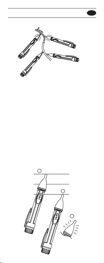
1. Test probe.
2. Detection result Indication area.
(Red light/Green light)
3. Clip.
4. Battery cover.
5. Function key.
6. Phase sequence detection mode indication.
(Red light / Green light)
7. Voltage detection mode indication.
(Yellow light)
4
3
1
2
7
5
6
7
6
5
3

VP-2 EN
Switch detection mode
Voltage detection
Press function key to switch Voltage/Phase
detection mode.
On AC Voltage detection mode: the Yellow
light of this mode ashing.
Phase rotation detection mode: the Red light
of this mode ashing.
While detecting the voltage >100Vac of the
conductor, the Yellow light of this mode is
still on and the Red light in the Detection
result indication area is ashing with beeping
intermittently.
The higher voltage with quicker intermittency
Click
Voltage test at insulated conductors.
Power On/O
Auto Power O
Press function key for 1 seconds to turn the
VP2 on/o.
The detectors will automatically power o
after approximately idle 5 minutes.
4
VP-2 EN
Phase sequence indication
1. Test on 1st line, the Red light of this mode
is ashing once/sec with beeping, keep the
test on L1 until the Green light of this mode
is stiil on.
2. Move the probe tip to 2nd line in 2
seconds, test on 2nd line the Green light of
this mode turns to ashing once/sec from
still on with beeping.
3. When test is completed the Green light of
this mode is O and the test result is
shown on detection result indication area
as mentioned in Phase sequence
indications.
Locating line interruptions.
Red light flashing
with Beeping
1
2
3
Line 3
Line 2
Line 1
5

VP-2 EN
Phase sequence indications
Note:
Battery replacement
The test result is to be one of light showings
below with 3 intermittent beeps in 5 seconds.
1.1st line ahead 2nd line: The Green light of
Detection result indication area is still on.
(1st line >> 2nd line)
2.1st line after 2nd line: The Red light in
Detection result indication is still on.(2nd
line >> 1st line)
3.The same phase eld indication :
The Green Light in Detection result
indication is ashing.
4.Error indication : The Green light and Red
light in Detection result indication are
ashing alternately. Detection result
represented the relation of Line 1 and
Line2 and Line3(Left rotary / Left rotary).
5.The phase sequence test always requires
a countercheck during which the phase
sequence must change.
Always hold the device steady during the
measurements without wobbling.
Mains failures or a lacking mains quality might
aect the correct functioning of the device.
Unscrew the battery cover Remove
discharged batteries and insert new by
respecting the correct polarity. Close the
battery cover careful.
6

VP-2 EN
Maintenance
Cleaning
Do not attempt to repair this Detector. It
contains no user-serviceable parts. Repair
or servicing should only be performed by
qualied personnel.
Periodically wipe the case with a dry cloth
and detergent.
Do not use abrasives or solvents.
If the instrument is likely to remain unused
for a long period it is advised to remove the
batteries. Please think of our environment
when getting rid of used batteries. They
should be disposed in a place suitable for
hazardous waste.
WARNING
7

VP-2 EN
Specications
Auto Power O : Approx 5 minutes
Voltage range : 100VAC~1000 VAC
Frequency : 45 ~ 65 Hz
Overvoltage category :
Designed to meet IEC 61010 & UL61010
CAT III 1000 VAC, CAT IV 600 VAC
CAT Application eld
I The circuits not connected to mains.
II The circuits directly connected to Low-
voltage installation.
III The building installation.
IV The source of the Low-voltage
installation.
Protection category : IP 53
Battery Life : 150 hours (standby)
Pollution Degree: 2
Operating temperature :
-10 °C ~ 50 °C
-10 °C ~ 40 °C (≤ 75% RH)
40 °C ~ 50 °C (≤ 45% RH)
Storage temperature : -20 to 60 °C for
current, 0 to 80% RH (batteries not tted).
Power supply : 2x AAA, 1.5 V LR03
Dimensions :
20.6mm(W) x 151mm(L) x 25.2mm(D)
Weight : approx. 40 g (incl. batteries)
Drop Protection : 4 feet drop to hardwood on
concrete oor.
8

VP-2 EN
Limited Warranty
The testers are subject to stringent quality
controls. If in the course of normal daily
use a fault should occur, we provide 3 year
guarantee (only valid with invoice) .
Faults in manufacture and materials will be
rectied by us free of charge, provided the
tester has not been tampered with, and is
returned to us unopened.
Damage due to dropping, abuse ormisuse is
not covered.
Our service department will promptly repair
any fault that occur outside the guarantee
period.
This instruction manual has been prepared
with great care.
No liability is accepted for the correctness
and completeness of the data and illustra-
tions it contains.We reserve the right to make
technical alterations.
9
Table des matières
Langues :
Autres manuels APPA Équipement de test


Manuels Équipement de test populaires d'autres marques

SMART
SMART KANAAD SBT XTREME 3G Series Manuel utilisateur

Agilent Technologies
Agilent Technologies BERT Serial Manuel utilisateur

Agilent Technologies
Agilent Technologies N3280A Manuel utilisateur

Vernier
Vernier Go Direct Voltage Manuel utilisateur

Lifeloc
Lifeloc R.A.D.A.R. Manuel utilisateur

Fluke
Fluke T5-600 Instructions d'utilisation et d'installation


