Apeks XTX FSR Manuel utilisateur
TECHNICAL SUPPORT
APEKS MARINE EQUIPMENT LTD, NEPTUNE WAY, BLACKBURN, LANCASHIRE. BB1 2BT
MAINTENANCE MANUAL
FOR
AUTHORISED TECHNICIANS
Document No. AP5825F
Issue 1
10/11/2013
XTX FSR & FST FIRST
STAGE REGULATOR

2
XTX FSR & FST First Stage Regulator Maintenance Manual
Change
No.
Change
Request No.
Description & Comments: Change
Date
New Issue
No.
Changed
By:
Approved
By:
AMENDMENTS RECORD:
Amendments and approval of this document can only be carried out by the relevant people listed on the Approved list of
signatures, which is listed in the Apeks Quality Manual. To instigate a change, a Task / Change request form, (Form No.
‘DESI/10002’), must be completed and passed to the relevant person(s) for approval which are listed on the Approved List of
Signatures. When approval has been granted and recoreded this table can then be completed and the document up issued.

3
XTX FSR & FST First Stage Regulator Maintenance Manual
Contents
COPYRIGHT NOTICE ............................................................................................................................................... 4
INTRODUCTION ....................................................................................................................................................... 4
WARNINGS, CAUTIONS & NOTES ......................................................................................................................... 4
SCHEDULED SERVICE ........................................................................................................................................... 4
GENERAL GUIDELINES .......................................................................................................................................... 4
GENERAL CONVENTIONS ...................................................................................................................................... 5
DISASSEMBLY PROCEDURES............................................................................................................................... 5
REASSEMBLY PROCEDURES................................................................................................................................ 7
IMMERSION TESTING ........................................................................................................................................... 11
TABLE 1 - TROUBLESHOOTING GUIDE .............................................................................................................. 12
TABLE 2 - RECOMMENDED TOOL LIST .............................................................................................................. 13
TABLE 3 - RECOMMENDED LUBRICANTS AND CLEANERS ........................................................................... 14
CLEANING AND LUBRICATION PROCEDURE .................................................................................................... 15
TABLE 4 -TORQUE SPECIFICATIONS ................................................................................................................. 16
TABLE 5 - TEST BENCH SPECIFICATIONS ......................................................................................................... 16
FSR XTX200 EXPLODED PARTS DRAWING ....................................................................................................... 17
FST XTX100 EXPLODED PARTS DRAWING ........................................................................................................ 18

4
XTX FSR & FST First Stage Regulator Maintenance Manual
COPYRIGHT NOTICE
This manual is copyrighted, all rights reserved. It may not,
in whole or in part, be copied, photocopied, reproduced,
translated, or reduced to any electronic medium or machine
readable form without prior consent in writing from Apeks
Marine Equipment Ltd. It may not be distributed through the
internet or computer bulletin board systems without prior
consent in from Apeks Marine Equipment Ltd.
©2013 Apeks Marine Equipment Ltd.
FSR & FST First Stage Maintenance Manual
(AP5825F Issue 8)
INTRODUCTION
This manual provides factory prescribed procedures for the
correct maintenance and repair of the Apeks FSR & FST rst
stage regulators. The model shown in this manual is the FSR,
although the FST differs in appearance, most components
are identical. It is not intended to be used as an instructional
manual for untrained personnel. The procedures outlined
within this manual are to be performed only by personnel
who have received factory authorised training through an
Apeks Service & Repair Seminar. If you do not completely
understand all of the procedures outlined in this manual,
contact Apeks to speak directly with a Technical Advisor
before proceeding any further.
WARNINGS, CAUTIONS & NOTES
Pay special attention to information provided in warnings,
cautions, and notes that are accompanied by one of these
symbols:
WARNINGS indicate a procedure or situation that
may result in serious injury or death if instructions
are not followed correctly.
CAUTIONS indicate any situation or technique that
will result in potential damage to the product, or
render the product unsafe if instructions are not
followed correctly.
NOTES are used to emphasise important points, tips,
and reminders.
SCHEDULED SERVICE
It is recommended that the Apeks FSR & FST rst stage
regulators should be examined annually regardless of usage.
A full serviced should be performed every two years.
However, If at all unsure about the correct functioning of
the Apeks rst stage, then it must be ofcially inspected
immediately.
All service and inspection details need to be documented
in the Regulator Service Record in the back of the Owner’s
Manual to keep the Limited Lifetime Warranty in effect.
An Ofcial Inspection consists of:
1. A pressurised immersion test of the entire unit to
check for air leakage.
2. Checking for stable medium pressure that is within
the acceptable range.
3. Checking that all parts are tightly fastened together
and that no parts are loose.
4. A visual inspection of the Environmental Diaphragm
looking for tears or holes and checking the general
condition.
5. A visual inspection of any lters for debris or dis-
colouration.
6. Pulling back hose protectors and checking that the
hoses are secure in the hose crimps.
If a regulator fails steps 1,2, or 3 the entire regulator should
be serviced. If a regulator fails 4 or 5 it will be up to the
technician’s discretion whether or not a full service is re-
quired. Failure of step 6 requires replacement of the Hose.
GENERAL GUIDELINES
1. In order to correctly perform the procedures outlined
in this manual, it is important to follow each step
exactly in the order given. Read over the entire
manual to become familiar with all procedures and
to learn which specialty tools and replacement parts
will be required before commencing disassembly.
Keep the manual open beside you for reference while
performing each procedure. Do not rely on memory.
2. All service and repair should be carried out in a work
area specically set up and equipped for the task.
Adequate lighting, cleanliness, and easy access to all
required tools are essential for an efcient repair facil-
ity.
3. During disassembly, reusable components should be
segregated and not allowed to intermix with non-
reusable parts or parts from other units. Delicate
parts, including inlet ttings and valve seats which
contain critical sealing surfaces, must be protected
and isolated from other parts to prevent damage
during the cleaning procedure.
4. Use only genuine Apeks parts provided in the 1st
stage service kit (AP0241). DO NOT attempt to
substitute an Apeks part with another manufacturer’s,
regardless of any similarity in shape or size.
5. Do not attempt to reuse mandatory replacement
parts under any circumstances, regardless of the
amount of use the product has received since it was
manufactured or last serviced.
6. When reassembling, it is important to follow every
torque specication prescribed in this manual,
using a calibrated torque wrench. Most parts are
made of either marine brass or plastic, and can be
permanently damaged by undue stress.

5
XTX FSR & FST First Stage Regulator Maintenance Manual
Pinch Method
Press upwards on
sides of ‘O’ Ring
to create a protru-
sion. Grab ‘O’ Ring
or insert ‘O’ Ring
tool at protrusion.
Removal of hose
Removal of Blanking Plugs
GENERAL CONVENTIONS
Unless otherwise instructed, the following terminology and
techniques are assumed:
1. When instructed to remove, unscrew, or loosen a
threaded part, turn the part anti-clockwise.
2. When instructed to install, screw in, or tighten a
threaded part, turn the part clockwise.
3. When instructed to remove an ‘O’ Ring, use the pinch
method (see gure below) if possible, or use a brass,
aluminium or plastic ‘O’ Ring removal tool. Avoid using
hardened steel picks, as they may damage ‘O’ Ring
sealing surfaces. All ‘O’ Rings that are removed are
discarded and replaced with brand new ‘O’ Rings.
4. The following acronyms are used throughout the
manual: MP is Medium Pressure; HP is High Pressure;
PN is Part Number.
5. Numbers in parentheses reference the key numbers
on the exploded parts schematics. For example, in the
statement, “...remove ‘O’ Ring (4) from...”, the number
4 is the key number to the Spring Carrier ‘O’ Ring.
DISASSEMBLY PROCEDURES
NOTE: Before performing any disassembly, refer
to the exploded parts drawing, which references all
mandatory replacement parts. These parts should be
replaced with new, and must not be reused under any
circumstances - regardless of the age of the regula-
tor or how much use it has received since it was last
serviced.
CAUTION: Use only a plastic, brass or aluminium
‘O’ Ring removal tool (PN AT79) when removing
‘O’ Rings to prevent damage to the sealing
surface. Even a small scratch across an ‘O’ Ring
sealing surface could result in leakage. Once an
‘O’ Ring sealing surface has been damaged, the
part must be replaced with new. DO NOT use a
dental pick, or any other steel instrument.
1. Using a 9/16 spanner, remove all of the hoses from the
rst stage. Remove the ‘O’ Ring from inside the Hose
Swivel. Exercise caution not to scratch the ‘O’ Ring
groove. Remove the ‘O’ Ring from the Hose Nut end of
the Hose.
2. Pull back the two
Hose Protectors and
inspect the Hose
Crimps. If either
Crimp is damaged or
the Hose is pulling
out of the crimp then
the Hose must be
replaced.
3. Using a 5mm Allen
key remove all of the
MP and HP blanking
plugs.
4. Remove all of the
‘O’ Rings from the
Blanking Plugs.
5. Using the First Stage
Work Handle (PN
AT48) clamp the
regulator in a vice.
6
XTX FSR & FST First Stage Regulator Maintenance Manual
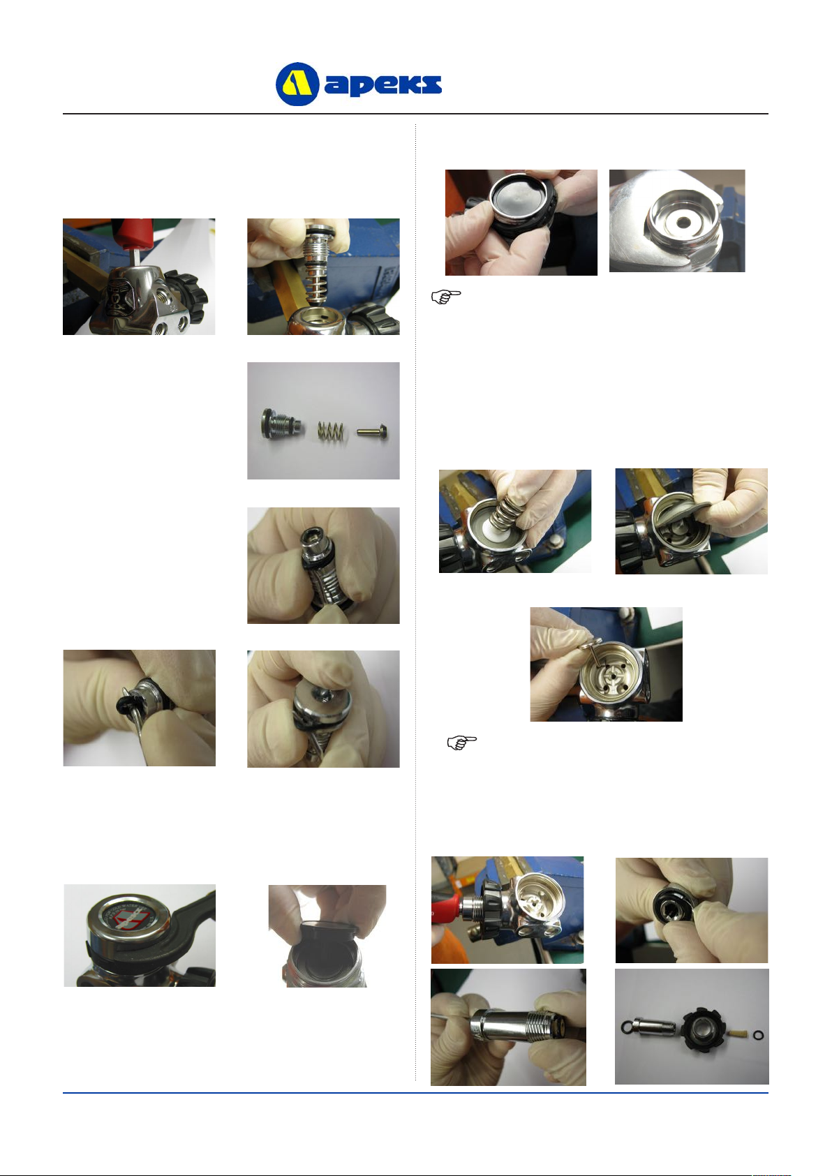
Removal of Balance Plug Assembly
Removal of Dry Sealed Chamber
NOTE: If the First Stage has a DIN Connection, go
to step 13: if it has a Yoke Connection follow step 14.
Removal of Din Connection
NOTE: The thickness of the spanner must not
exceed 11mm or it will not t between the thread and
the ange. The correct spanner can be purchased
from Apeks (PN AT47)
6. Using a 6mm Allen key unscrew the Balance Plug (18)
and withdraw the Balance Plug assembly.
7. Separate the Balance
Plug assembly by
pulling on each end.
8. Remove ‘O’ Rings
(16,12,17) from the
Balance Plug (18),
taking care not to
scratch the ‘O’ Ring
grooves.
9. Using a C Spanner (PN AT30) unscrew the
Environmental End Cap (1). Remove the Load
Transmitter (3) from inside the Diaphragm Clamp (6).
10. Remove the Moulded Ring (5) and using a 34mm
open ended spanner unscrew the Diaphragm Clamp (6).
11. Remove the Spring (7) & Spring Carrier (8). Replace
three of the MP blanking plugs (no ‘O’ Rings required)
and screw them in nger tight. Put the nozzle of a
compressed air blow gun in the remaining MP port and
blow a sharp blast of air to remove the diaphragm (9).
Remove the MP blanking plugs.
12. Remove the Valve Lifter (10) from the Valve Body (11).
13. Using a 6mm Allen key, unscrew the DIN Connection
Assembly and separate into four pieces. Remove the ‘O’ Ring
(23) from the end of the Handwheel connector (30).

7
XTX FSR & FST First Stage Regulator Maintenance Manual
Removal of Yoke Connection
Removable
HP Valve Seat XTX200 HP
Seat Tool
(PN AT53)
14. Unscrew the Yoke Clamp Screw (24) and remove the
Protective Cap (22) from the Yoke Clamp (19). Using a
3/4” A/F spanner, loosen the Yoke Clamp Connector
(20). Unscrew the Yoke Connector and Yoke Clamp.
Remove the ‘O’ Ring from the Yoke Clamp Connector
(20).
15. Insert a dowel
through the open end
of the Yoke Clamp
Connector (20) and
push out the Disc
Filter (21).
Removal of Removable HP Valve Seat (FSR Only)
CAUTION: Before proceeding, make sure
you are working over a padded work
surface: otherwise, the Removable HP Valve
Seat (13) may be damaged during removal.
16. To remove the HP Valve Seat (13) from the FSR Valve
Body (11) locate the end of the HP Seat Tool (PN
AT53) inside the small hole. Gently slide the tool into
the hole, this will push the HP Valve Seat out of the
bottom of the Valve Body (11).
17. Remove the ‘O’ Ring (12) from the HP Valve Seat (13).
This Ends Disassembly
Before starting reassembly, perform parts cleaning
and lubrication according to the procedures
outlined in ‘Cleaning & Lubrication’ on page 15.
REASSEMBLY PROCEDURES
Fitting of Removable HP Valve Seat (FSR Only)
1. Install a new lubricated ‘O’ Ring (12) onto the
Removable HP Valve Seat (13). Locate the Removable
HP Valve Seat onto the end of the HP Seat Tool (PN
AT53). Ensure that the seating face of the Valve Seat
is against the Seat Tool. Firmly push the Seat Tool
into the Valve Body (11) until the Removable HP Valve
Seat is located at the bottom of the bore.
WARNING: The regulator will not operate if the
Removable HP Valve Seat is inserted into the Valve
Body incorrectly.
NOTE: A slot on the at face of the HP valve seat has
been added to identify the way of assembly

8
XTX FSR & FST First Stage Regulator Maintenance Manual
Assembling and tting of Yoke Connection
NOTE: Ensure that the ‘O’ Ring is retained in the
Connector after the Conical Filter has been tted.
CAUTION: If the Yoke Clamp Assembly is not
held vertically whilst it is screwed into the
Valve Body, the ‘O’ Ring in the end of the Yoke
Clamp Connector may not remain in the correct
position.
Assembling and tting of DIN Connection
CAUTION: If the Handwheel Connector
Assembly is not held vertically whilst it is
screwed into the Valve Body, the ‘O’ Ring in the
end of the Handwheel Connector may not remain
in the correct position.
1. Insert a new Disc Filter (21) with the smooth side out,
into the Yoke Clamp Connector (20). Install a new
lubricated ‘O’ Ring (12) into the end of the Connector.
2. Insert the Yoke Clamp Connector (20) through the
Yoke Clamp (19). With the Valve Body held so that
the inlet connection port points down, screw the Yoke
Clamp Connector into the Valve Body (11) until nger
tight.
3. Secure the Valve Body (11) back into the vice using the
First Stage Work Handle (PN AT48). Tighten the Yoke
Clamp Connector using a 3/4” A/F spanner. Install the
Protective Cap (22) with the logo facing outwards, onto
the Yoke Clamp (19). Screw the Yoke Clamp Screw
(24) back into the Yoke Clamp (19), until the Protective
Cap (22) is retained in place.
4. Install a new ‘O’ Ring (23) into the face of the
Handwheel Connector (30). Install a new lubricated
‘O’ Ring (12) into the opposite end of the Connector.
Install the Conical Filter (35) into the Connector,
through the ‘O’ Ring.
5. Insert the threaded end of the Handwheel Connector (30)
through the threaded end of the Handwheel (29). With
the Valve Body held so that the inlet connection port
points down, screw the Handwheel Connector into the
Valve Body (11) until nger tight.
6. Secure the Valve Body (11) back into the vice using
the First Stage Work Handle (PN AT48). Tighten the
Handwheel Connector (30) using a 6mm Allen key bit
in a torque wrench to 20 Nm.

9
XTX FSR & FST First Stage Regulator Maintenance Manual
This Ends Re-assembly
Fitting of the Dry Sealed Chamber
7. Drop the Valve Lifter (10) through the centre hole of
the Valve Body (11). Press a new Diaphragm (9) into
the Body. Run your nger around the edge of the
diaphragm to make sure it is properly seated.
8. Place the spring carrier (8) and Spring (7) centrally onto
the diaphragm (9).Thread the Diaphragm Clamp (6) onto the
Valve Body (11), making sure that the Spring (7) remains on
the Spring Carrier (8), until hand tight. Using a 34mm Span-
ner (PN AT47) tighten the Diaphragm Clamp (6) until there is
metal to metal contact. Ret the Moulded Ring (5).
9. Fit new Lubricated ‘O’ Rings (12 & 17) onto the H.P.
Balance Plug. Install a new lubricated ‘O’ Ring (16)
into the end of the H.P Balance Plug. Ensure that the ‘O’
Ring is ush.
10. Press the Spring (15) onto the end of the H.P. Balance
Plug. Carefully insert a new H.P. Valve (14) into the
H.P Balance plug assembly.
11. Insert the H.P. Balance Plug (18) into the Valve Body
(11) and tighten using a 6mm Allen key bit in a torque
wrench to 8 Nm.

10
XTX FSR & FST First Stage Regulator Maintenance Manual
Adjusting the First Stage
CAUTION: If the pressure gauge rapidly exceeds
11 bar, then there is a HP leak. Quickly close the
cylinder valve and purge the regulator. Refer to
the troubleshooting table for the causes of the
leak.
WARNING: Compressed air can be highly
explosive and is dangerous if misused. Ensure
cylinder valve is opened slowly. Use Eye and
Ear Personal Protective Equipment when
performing any tests involving Compressed
air.
Final Assembly
NOTE: The Pour Moulded Hydrostatic Diaphragm
(2) in the XTX does not need to be replaced with a
new one unless it is deemed damaged or worn by the
technician.
1. Attach the rst stage
(with no Blanking
Plugs tted) to a fully
charged 232 or 300
bar cylinder. Slowly
open the cylinder
valve, this will
remove any particles
or contaminants from
the rst stage.
2. Install new
lubricated ‘O’ Rings
(12,27) on all of
the Blanking Plugs
(26,28). Using a
5mm Allen key,
install all of the
Blanking Plugs into
the Valve Body.
3. Attach a MP test gauge (0 - 20 bar) to a medium
pressure hose and thread the hose into a MP port.
If your test gauge does not have an over pressure
relief valve, you must also attach a properly adjusted
second stage to the rst stage to act as the relief valve
in case of a HP leak. Make sure Blanking Plugs are
installed in any open ports.
4. Assuming there are no leaks, close the cylinder valve
and depressurise the regulator by opening the gauge
relief valve or by pressing the purge button of the
second stage regulator. Adjust the medium pressure
by turning the Spring Adjuster (4): Turning in the
Spring Adjuster increases the MP; Turning out the
Spring Adjuster decreases the MP. Turn the Spring
Adjuster in 1/8th turn increments and purge the relief
valve several times after each adjustment. When the
MP is between 9 and 10 bar , purge the relief valve
on and off 10-15 times. After cycling, watch the gauge
needle. The rst stage MP should “lock-up” between 9
and 10 bar. Make any adjustments as necessary. Allow
the rst stage to stay pressurised for several minutes
and check the MP again to make sure it remains
“locked-up” between 9 and 10 bar. If the MP creeps
upward more than 0.25 bar, then there is a leak. Refer
to the troubleshooting table for possible causes.
5. Close the cylinder valve and depressurise the
regulator by opening the gauge relief valve or by
pressing the purge button of the second stage
regulator. Close the relief valve and repressurise
the system. The MP should still read between 9 and
10 bar. If the pressure reading is different than the
original setting, repeat steps 3 and 4 until the MP is
stable.
1. With the regulator still pressurised, insert the Load
Transmitter (3) into the Diaphragm Clamp (6). Press a
new Hydrostatic Diaphragm (2) into the Environmental
End Cap (1) (If required).
Ce manuel convient aux modèles suivants
3
Table des matières
Autres manuels Apeks Contrôleurs

Apeks
Apeks Egress Manuel utilisateur

Apeks
Apeks Flight Manuel utilisateur

Apeks
Apeks FSR Series Manuel utilisateur

Apeks
Apeks DST Manuel utilisateur

Apeks
Apeks ATX Second Stage Manuel utilisateur

Apeks
Apeks XL4 SECOND STAGE Manuel utilisateur

Apeks
Apeks TEK3/XTX50 Manuel utilisateur

Apeks
Apeks MTX-R Manuel utilisateur

Apeks
Apeks TX100 Manuel utilisateur

Apeks
Apeks GX300 Manuel utilisateur


