Anywave RF Manuel utilisateur

ANYWAVE
RF Switch Controller
User Manual
SRFC-1+1-N
Version 2.0
January 6th 2017

RF Switch Controller User Manual
RF-SWITCH-USR-DOC-V2.0, 1/6/2017 Page 2 of 20
Copyright Notice
Copyright © Anywave Communication Technologies, Inc. 2014, All rights reserved.
No part of this publication may be reproduced, translated, transcribed, stored in a
retrieval system, or transmitted into any form or by any means, without the express
written permission of Anywave Communication Technologies, Inc.
Disclaimer
Information provided by Anywave Communication Technologies is believed to be
accurate and complete; however, no liability can be assumed for its use.
The manufacturer makes no representations or warranties, either expressed or implied,
by or with respect to anything in this manual, and shall not be liable for any implied
warranties of fitness for a particular purpose or for any indirect, special, or
consequential damages. Information in this document is subject to change without
notice and does not represent a commitment on the part of the manufacturer.
USE OF THIS PRODUCT IN A MANNER OTHER THAN DESCRIBED IN THIS
MANUAL MAY RESULT IN DAMAGE TO THE EQUIPMENT AND/OR
PERSONAL INJURY.
PLEASE READ THIS MANUAL IN ITS ENTIRETY BEFORE ATTEMPTING TO
INSTALL THE EQUIPMENT. CONTACT ANYWAVE WITH ANY QUESTIONS
OR CONCERNS YOU MAY HAVE.
Anywave Communication Technologies Inc.
300 Knightsbridge Parkway, Suite 150, Lincolnshire, IL 60069
Tel: (847) 415-2258
Fax: (847) 415-2112
http://www.anywavecom.com/en/

RF Switch Controller User Manual
RF-SWITCH-USR-DOC-V2.0, 1/6/2017 Page 3 of 20
Unpacking
Carefully unpack the equipment and perform a visual inspection to determine if any
apparent damage has occurred during shipment. Please notify the delivery carrier and
Anywave immediately if shipment damage has occurred. Retain all original shipping
materials.
Please locate and reference the Packing Check List to verify you have received all
components of your system. Retain the Packing Check List for future reference.
Also, please identify and remove all packing materials and supports (foam pads, etc.)
prior to initial turn on of the equipment.
Returns and Exchanges
Written approval and a Return Authorization Number (RAN) are required from
Anywave for all equipment returns. Please direct all return inquiries to the Anywave
number and Serial Number(s) of the equipment. Complete details regarding the nature
and circumstances of your return must be included in your RAN request. Proper
handling and return shipping instructions will be provided with an approved RAN
number.
Technical Support
Technical support and troubleshooting assistance for Anywave Transmitters is
available through theAnywave Service Department during normal business hours (8:00
AM - 5:00 PM CST) at (847) 415-2258.Email questions to
Note: For all service and support requests, you will need to provide the Serial Number
of the equipment with your Sales Order number. For future reference, please record that
information here:________________________________________
RF Switch Controller User Manual
RF-SWITCH-USR-DOC-V2.0, 1/6/2017 Page 4 of 20
WARNING
THE VOLTAGES, CURRENTS, AND RF ENERGY IN THIS EQUIPMENT
ARE DANGEROUS. PERSONNEL MUST AT ALL TIMES OBSERVE ALL
SAFETY WARNINGS, INSTRUCTIONS, AND REGULATIONS.
IN THE CASE OF EMERGENCY, ENSURE THAT ALL POWER HAS BEEN
DISCONNECTED.
ALWAYS DISCONNECT POWER BEFORE REMOVING COVERS,
ENCLOSURES, OR SHIELDS. DO NOT PERFROM SERVICE ON THE
EQUIPMENT WHEN ALONE OR FATIGUED. KNOW YOUR EQUIPMENT
AND DO NOT TAKE RISKS.
This manual is provided as a general guide for trained and qualified personnel well
aware of the dangers inherent in handling potentially hazardous electrical transmission
equipment.
The installation, operation, maintenance and service of this equipment involves risks
both to personnel and equipment, and must ONLY be performed by qualified personnel
exercising due care. Anywave Communication Technologies, Inc. shall not be
responsible for injury or damage resulting from improper handling or from the use of
improperly trained or inexperienced personnel performing such tasks.
All local building and electrical codes as well as fire protection standards must be
observed in the installation and operation of the equipment.

RF Switch Controller User Manual
RF-SWITCH-USR-DOC-V2.0, 1/6/2017 Page 5 of 20
Contents
1Introduction ......................................................................................6
2System Interconnect Diagram ..........................................................6
3Auto Switching - Setup and Operation.............................................7
4Manual Switching - Setup and Operation.......................................13
5Switching Operations - Summary...................................................16

RF Switch Controller User Manual
RF-SWITCH-USR-DOC-V2.0, 1/6/2017 Page 6 of 20
1Introduction
This User Manual contains instructions to safely setup and operate the Anywave
RF Switch Controller. The Anywave RF Switch Controller is implemented for
applications requiring automatic or manual switching between multiple transmitters.
Please note that trained and qualified personnel are required to install, maintain, and
service this transmission equipment.
2System Interconnect Diagram
The diagram below outlines the RF Switch Controller connections for switching
between two Anywave LPTV Transmitters. The Switch Controller has a default
IPaddress of 192.168.1.210 with login, user: anywavecom, password: anywavecom.
Note: Please use the Anywave supplied DB9 serial cables to connect the Switch
Controller to each PA.
Figure 1
(IPaddress: 192.168.1.210)
RF Switch Controller User Manual
RF-SWITCH-USR-DOC-V2.0, 1/6/2017 Page 7 of 20
3Auto Switching - Setup and Operation
Auto mode: Set the switch controller to Remote mode from its front panel
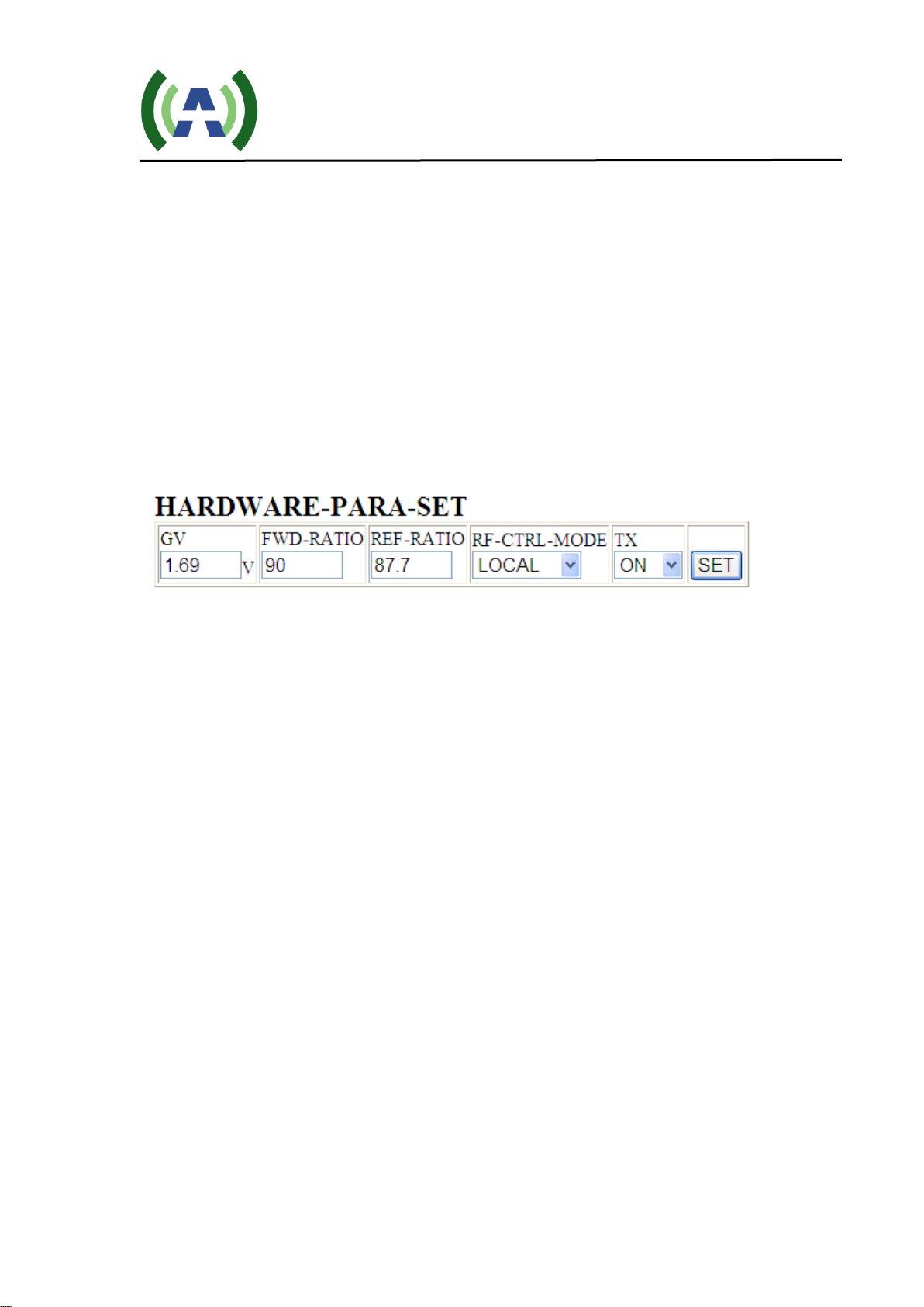
1) Log into the web interface on both amplifiers, and change
their control mode from LOCAL to REMOTE (note: the coaxial
switching only works when both amplifiers are in REMOTE mode). The
RF-CTRL-MODE setting is shown in Figure 2. When switched to
REMOTE mode, the amplifiers’ front panel RF On/Off buttons will be
inactive.
Figure 2
2) Connect all cables/wires as shown in Figure 1, and then turn
on the exciters, amplifiers, coaxial switch and switch controller.
If any power amplifier has a proper output power that is higher than a
pre-set minimum level, then the amplifier can be determined as
VALID. If both PAs are valid, then amplifier A will be selected as the
default PA (Note: The PA connected to REMOTE 1 on the back panel
of the switch controller is recognized the amplifier A, and the PA
connected to REMOTE 2 is recognized as amplifier B).
If there is a problem with the serial port communication between the
PAs and the controller, it will show error on STATUS->
LPTV_A_UART or LPTV_B_UART on the web page as shown in
figure 3.

RF Switch Controller User Manual
RF-SWITCH-USR-DOC-V2.0, 1/6/2017 Page 8 of 20
Figure 3
Figure 4
The Coaxial Switch Controller’s web pages are shown in figures
3 and 4. AMP_FWD_MIN is the minimum output power that is user to
determine VALID amplifier and it can be use adjusted.
AMP_CHANGE_TIMES with the default setting of 3 means the total
number of times that the switch controller will try to switch back and forth
between two amplifiers using the coaxial switch before finally stopping.

RF Switch Controller User Manual
RF-SWITCH-USR-DOC-V2.0, 1/6/2017 Page 9 of 20
3) Switching Procedure: As shown in Figure 3, if the output power of
the amplifier A (now 47W) is less than the AMP_FWD_MIN (set to be
50W), then the Controller will check for a few more times to make sure the
output power is constantly lower than the threshold. This detection period
will take about 30 seconds. Once the power level is confirmed to be lower
than the threshold, then the Controller will switch from amplifier A to
amplifier B using the coaxial switch. The Switch over process is as follows:
first the Controller will mute both amplifiers remotely, then the Controller
will use the coaxial switch to switch amplifier B to the antenna and
amplifier A to the dummy load, as you can see the real time status showing
in LPTV_USED has changed from LPTV_A to CHANGE TO B in
FIG. 5, then the Controller will unmute amplifier B. Amplifier B will be
ramped up from zero to the rated power as shown in figure 6 and
7. Amplifier A RF remains off.
Figure 5
(Detected LPTV_A output is less than AMP_FWD_MIN, shut down both amplifiers,
and to switch to LPTV_B)

RF Switch Controller User Manual
RF-SWITCH-USR-DOC-V2.0, 1/6/2017 Page 10 of 20
Figure 6
(Amplifier B power slowly ramping up)
Figure 7
(Amplifier B at rated power)
4) Likewise, when the output power of amplifier B is less than
AMP_FWD_MIN, the same steps as in step 3 are performed, shown in FIG. 8, 9 and
10.
Ce manuel convient aux modèles suivants
1
Table des matières


