ANPVIZ HK Series Manuel utilisateur

User
Manual
EN / DE / FR / ES / IT Version
HK Series
Network Bullet Camera

Thank you very much for choosing ANPVIZ.
Our products are supported by the world's first video monitoring manufacturers.
and they have adopted military level of protection.
It is our top priority to ensure your data safety and offer you a satisfactory service.
We strongly recommend that you set up an appropriate password for your device and save it
also set up security questions and reserved email to ensure you can reset password by yourself.
If you have any questions, please feel free to email us at support@anpvizsecurity.com
Or visit https://www.anpvizsecurity.com/download/
Please download Client software and user manuals from our download center
https://www.anpvizsecurity.com/downloadcenter.html
- 1 -
EN

The Manual includes instructions for using and managing the product Picture, charts,
images and all other information hereinafter are for description and explanation only.
The information contained in the Manual is subject to change, without notice, due to
firmware updates or other reasons. Please find the latest version in the company
website. Please use this user manual under the guidance of professionals.
About this Manual
REGARDING TO THE PRODUCT WITH INTERNET ACCESS, THE USE OF PRODUCT
SHALL BE WHOLLY AT YOUR OWN RISKS. OUR COMPANY SHALL NOT TAKE ANY
RESPONSIBILITES FOR ABNORMAL OPERATION, PRIVACY LEAKAGE OR OTHER
DAMAGES RESULTING FROM CYBER ATOCK, HACKER ATTACK VIRUS
INSPECTION, OR OTHER INTERNET SECURITY RISKS HOWEVER, OUR
COMPANY WILL PROVIDE TIM ELY TECH NIC AL SUPPORT IF REQUIRED.
SURVEILLANCE LAWS VARY BY JURISDICTION. PLEASE CHECK ALL RELEVANT
LAWS IN YOUR JURISDICTION BEFORE USING THIS PRODUCT IN ORDER TO
ENSURE THAT YOUR USE CONFORMS THE APPLICABLE LAW. OUR COMPANY
SHALL NOT BE LIABLE IN THE EVENT THAT THIS PRODUCT IS USED WITH
ILLEGITIMATE PURPOSES.IN THE EVENT OF ANY CONFLICTS BETWEEN THIS
MANUAL ANDTHE APPLICABLE LAW, TH E LATER PREVAILS.
FCC Information
Please take attention that changes or modification not expressly approved by the party
responsible for compliance could void the users authority to operate the equipment.
FCC compliance: This equipment has been tested and found to comply with the limits
for a Class B digital device, pursuant to part 15 of the FCC Rules.
These limits are designed to provide reasonable protection against harmful interference
in a residential installation. This equipment generates, uses and can radiate radio
frequency energy and, if not installed and used in accordance with the instructions, may
cause harmful interference to radio communications.
However, there is no guarantee that interference will not occur in a particular installation.
If this equipment does cause harmful interference to radio or television reception, which
can be determined by turning the equipment off and on, the user is encouraged to try to
correct the interference by one or more of the following measures:
—Reorient or relocate the receiving antenna.
Legal Disclaimer
Regulatory Information
- 2 -

- 3 -
—Increase the separation between the equipment and receiver.
—Connect the equipment into an outlet on a circuit different from that to which the
receiver Is connected.
—Consult the dealer or an experienced radio/TV technician for help.
EU Conformity Statement
FCC Conditions
This device complies with part 15 of the FCC Rules. Operation is subject to the following
two conditions:
1. This device may not cause harmful interference.
2.This device must accept any Interference received. Including Interference that may
cause undesired operation
This product and - if applicable - the supplied accessories too are marked
with ( £ 'CE' and comply therefore with the applicable harmonized European
standards listed under the Low Voltage Directive 2015/35/EU, the EMC
Directive 2014/30/EU, the RoHS Directive 2011/65/EU.
2012/19/EU (WEEE directive): Products marked with this symbol cannot be
disposed of as unsorted municipal waste in the European Union. For proper
recycling, return this product to your Local supplier upon the purchase of
equivalent new equipment or dispose of it at designated collection points.
For more information, please see: www.recyclethis.info.
2006/66/EC (battery directive): This product contains a battery that cannot be
disposed of as unsorted municipal waste In the European Union. See the
product documentation for specific battery information. The battery is marked
with this symbol which may Include lettering to Indicate cadmium (Cd),
lead (Pb), or mercury (Hg). For proper recycling, return the battery to your
supplier or to a designated collection point For more Information,
please see: www.recyclethis.info.
Safety Instruction
These instructions are Intended to ensure that user can use the product correctly to
avoid danger or property loss. The precaution measure is divided into “Warnings” and
"Cautions"

- 4 -
Warnings: Serious Injury or death may occur if any of the warnings are neglected.
Cautions: Injury or equipment damage may occur if any of the cautions are neglected.
Warnings: Follow these safeguards to
prevent serious injury or death.
Cautions: Follow these precautions to
prevent potential injury or material damage.
Warnings
• Proper configuration of all passwords and other security settings is the responsibility of
the installer and/or end-user.
• In the use of the product you must be in strict compliance with the electrical safety
regulations of the nation and region. Please refer to technical specifications for detailed
information.
• In put voltage should meet both the SELV (Safety Extra Low Voltage) and the Limited
Power Source with 100~240 SC or 12 VDC according to the IEC60950-1 standard.
Please refer to technical specifications for detailed information.
• Do not connect several devices to one power adapter as adapter overload may cause
over-heating or a fire hazard.
• Please make sure that the plug is firmly connected to the power socket
• If smog odor or noise rise from the device, turn off the power at once and unplug the
power cable, and then please contact the service center.
Cautions
• Make sure the power supply voltage Is correct before using the camera.
• Do not drop the camera or subject it to physical shock,
• Do not touch senor modules with fingers. If cleaning Is necessary, use clean cloth with
a bit of ethanol and wipe it gently. If the camera will not be used for an extended period,
replace the lens cap to protect the sensor from d lit
• Do not aim the camera at the sun or extra bright places. Blooming or smearing may
occur otherwise (which Is not a malfunction), and affect the endurance of sensor at the
same time.
• The sensor may be burned out by a Laser beam, so when any Laser equipment is in
using, make sure that the surface of sensor will not be exposed to the laser beam.

- 5 -
• Do not place the camera In extremely hot, cold (the operating temperature shall be
-30°C to +60°C, or -40"C to +60*C if the camera model has an "H1 in its suffix), dusty or
damp Locations, and do not expose it to high electromagnetic radiation.
• To avoid heat accumulation, good ventilation is required for operating environment.
• Keep the camera away from liquid while In use.
• While in delivery, the camera shall be packed in its original packing, or packing of the
same texture.
1. Appearance Description
This series of cameras have two appearances shown as the figures below
Note: For cameras support power over Ethernet (PoE), the power is passed along with
data on Ethernet cabling. And a switch supports PoE function Is required.
Type I:
Bullet Camera Overview

- 6 -
Type II:
Bullet Camera Overview
2. Installation
• Make sure the device in the package is in good condition and all the assembly parts
are included.
• Hie standard power supply is PoE or12 VDC, please make sure your power supply
matches with your camera.
• Make sure all the related equipment is power-off during the installation.
• Check the specification of the products for the installation environment
• Make sure that the wall is strong enough to withstand four times the weight of the
camera and the bracket.
• Make sure that there is no reflective surface too close to the camera lens. The IR Light
from the camera may reflect back into the Lens causing reflection.
Only type I camera supports memory card installation, you can follow the steps to mount
and unmount the memory card.
Before you start:
2.1 Memory Card Installation

- 7 -
Steps:
1. Loosen the screws to remove the memory card slot cover.
2. Insert the memory card into the memory card slot.
3. (Optional)To unmount the memory card, push to get it ejected.
4. Screw the cover back to the camera.
Unscrew the Cover and Insert Memory Card
2.2 Ceiling Mounting
Both wall mounting and ceiling mounting are suitable for the bullet camera. Ceiling
mounting will be taken as an example in this section. And you can take steps of ceiling
mounting as a reference for wall mounting.
Before you start:
Steps:
1. Paste the drill template (supplied) to the desired mounting position on the ceiling.
2. Drill the screw holes in the ceiling according to the supplied drill template.

- 8 -
Note: Drill the cable hole. If adopting ceiling outlet to route the cable.
The Drill Template
3. Route the cables through the cable hole (optional), or the side opening.
4. Fix the camera on the ceiling with supplied screws.
Note:
• In the supplied screw package, both self-tapping screws, and expansion bolts are
contained.
• If the ceiling is cement expansion bolts are required to fix the camera. If the ceiling is
wooden, self-tapping screws are required.
- 9 -
5. Connect the corresponding power cord, and network cable.
6. Power on the camera, and set the network configuration (for details, refer to 3 Activate
and Access Network Camera) to check whether the Image Is gotten from the optimum
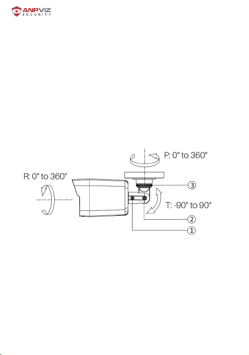
angle. If not, adjust the surveillance angle.
1) Loosen the No. 1 adjusting screw to adjust the rotation position [0* to 36。°ã].
2) Tighten the No.1 adjusting screw.
3) Loosen the No.2 adjusting screw to adjust the tilting position [-90* to 90"].
4) Tighten the No.2 adjusting screw.
5) Loosen the No.3 adjusting screw to adjust the pan position [0* to 3601.
6) Tighten the No.3 adjusting screw.
Note:
• For some camera models No.3 adjusting screw is replaced with fix ring. You can
loosen the fix ring to adjust the pan position.
• For some camera models, the tilting adjusting angle is 0°to 90°.
3-Axis Adjustment
• (Optional) Install the waterproof jacket Refer to 2.4 Install Network Cable Waterproof
Jacket for details.
2.3 Wall Mounting with Junction Box
• Both wall mounting and ceiling mounting are suitable forth© bullet camera. Wall
mounting will be taken as an example in this section. And you can take steps of wall
mounting as a reference for ceiling mounting.
• You need to purchase a junction box first.
Before you start:
Autres manuels pour HK Series
1
Table des matières
Autres manuels ANPVIZ Caméra de sécurité


