Anolis ArcPower 72/K2 Manuel utilisateur
version 1.7

2
Table of contents
1. Safety instructions ......................................................................................................... 3
2. Operating determinations.............................................................................................. 3
3.Description of the ArcPower 72/K2................................................................................ 4
4.Installation........................................................................................................................ 4
4.1.Connection to the mains ............................................................................................ 4
4.2.Mounting the ArcPower 72/K2 ................................................................................... 5
4.3.Conection cables........................................................................................................ 5
5.Installing instructions. .................................................................................................... 6
5.1.DMX operating ........................................................................................................... 6
5.2.Master-slave operating............................................................................................... 8
5.3. Operating via DyNet protocol .................................................................................... 9
6.ArcPower 72/K2 - Control menu map .......................................................................... 10
7.ArcPower 72/K2-DMX protocol .................................................................................... 11
8.Control board................................................................................................................. 12
8.1 Addressing the ArcPower 72/K2 ............................................................................. 12
8.2 Program running ...................................................................................................... 12
8.3 Manual mode ........................................................................................................... 13
8.4 Test sequences........................................................................................................ 14
8.5 Stand-alone mode.................................................................................................... 14
8.6 Special functions ...................................................................................................... 14
9.Control of the ArcPower 72/K2 via RS-232 ................................................................. 17
9.1Wiring an RS-232 serial port .................................................................................... 17
9.2 Selecting a zone....................................................................................................... 17
9.3 Setting a serial port of PC ........................................................................................ 17
9.4 Zone commands ...................................................................................................... 17
10.Technical Specications: ........................................................................................... 19
11. Replacing the fuse ..................................................................................................... 20
ArcPower 72/K2
3
CAUTION!
Unplug mains lead before opening the housing!
FOR YOUR OWN SAFETY, PLEASE READ THIS USER MANUAL CAREFULLY
BEFORE YOU INITIAL START - UP!
1. Safety instructions
Every person involved with installation and maintenance of this product has to:
- be qualiled
- follow the instructions of this manual
CAUTION!
Be careful with your operations. With a high voltage you can suffer
a dangerous electric shock when touching the wires inside the unit!
This product has left our premises in absolutely perfect condition. In order to maintain this condition and to
ensure a safe operation, it is absolutely necessary for the user to follow the safety instructions and warning
notes written in this manual.
To prevent from danger of accident ,the device has to be xed on at, non-f lam-
mable surface in compliance with the installing instruction included in this manual.
Important:
The manufacturer will not accept liability for any resulting damages caused by the non-observance of this
manual or any unauthorized modication to the product.
Always ground the unit.
The electric connection, repairs and servicing must be carried out by a qualied employee.
Do not connect this unit to a dimmer pack.
Use a source of AC power that complies with local building and electrical rules.AC power has to have both
overload and short circuit protection
2. Operating determinations
This product was designed for indoor use with Luxeon K2 LED´s modules only.In case of connecting
1W LED´s modules these modules will be destroyed!
If the unit has been exposed to drastic temperature uctuation (e.g. after transportation), do not switch it on
immediately. The arising condensation water might damage your unit. Leave the unit switched off until it has
reached room temperature.
Avoid brute force when installing or operating the unit.
When choosing the installation-spot, please make sure that the unit is not exposed to extreme heat, moisture
or dust.
Only operate the unit after having checked that the housing is rmly closed and all screws are tightly fas-
tened.
The maximum ambient temperature 40° C must never be exceeded.
Operate the unit only after having familiarized with its functions. Do not permit operation by persons not quali-
ed for operating the unit. Most damages are the result of unprofessional operation!
Please use the original packaging if the product is to be transported.
Please consider that unauthorized modications on the unit are forbidden due to safety reasons!
4
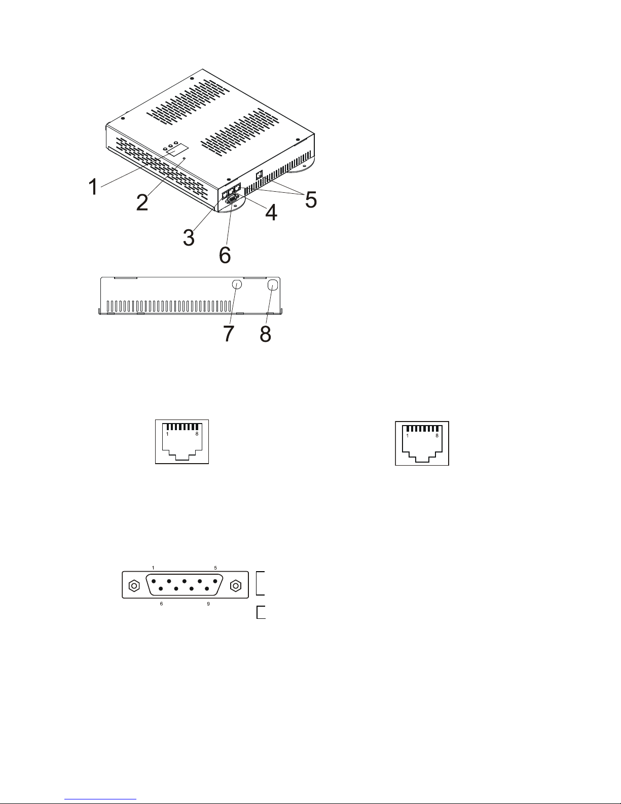
3.Description of the ArcPower 72/K2
DMX Input,Output LED zone Output
RJ45 socket RJ45 socket
Front view of the socket: Front view of the socket:
RS232 Output
Canon 9-pin male
Front view of the socket:
4.Installation
4.1.Connection to the mains
The ArcPower 72/K2 is equipped with auto-switching power supply that automatically adjusts to any 50/60Hz
AC power source from 100-240 Volts.
Carefully prepare the end of the the supply cord and t a suitable plug.A 3-prong grounding-type plug must be
1- Control board
2- Power Indicator
3- DMX Output
4- DMX Input
5- LED Zone outputs
6- RS 232 Output
7- Fuse Holder
8- Power Cord
Pin 1: Not connected Pin 5: Not connected
Pin 2: Not connected Pin 6: Data +
Pin 3: Not connected Pin 7: Data -
Pin 4: Not connected Pin 8: GND
Pin 1: Red LED + Pin 5: Red LED -
Pin 2: Green LED + Pin 6: Green LED -
Pin 3: Blue LED + Pin 7: Blue LED -
Pin 4: White LED + Pin 8: White LED -
Pin 1: Not connected
Pin 2: Received Data
Pin 3: Transmitted Data
Pin 4:
Pin 5: Signal Ground
Pin 6:
Pin 7:
Pin 8:
Pin 9: Not connected
5
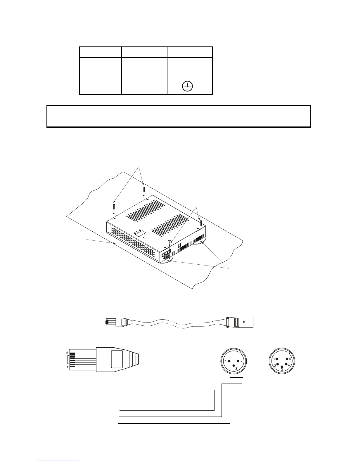
installed following the manufacturer´s instructions.The earth has to be connected!
Cord plug connections:
Cable Pin International
Brown Live L
Light blue Neutral N
Yellow/Green Earth
This device falls under protection class I.Therefore the ArcPower 72/K2 has to be
connected to a mains socket outlet with a protective earthing connection.
4.2.Mounting the ArcPower 72/K2
The ArcPower 72/K2 should be be placed on a non-f lammable f lat surface in any orientation and xed by the
4 screws.There are 4 mounting holes of diameter 5 mm in housing of the driver. Ensure that instalation place
is enough ventilated.
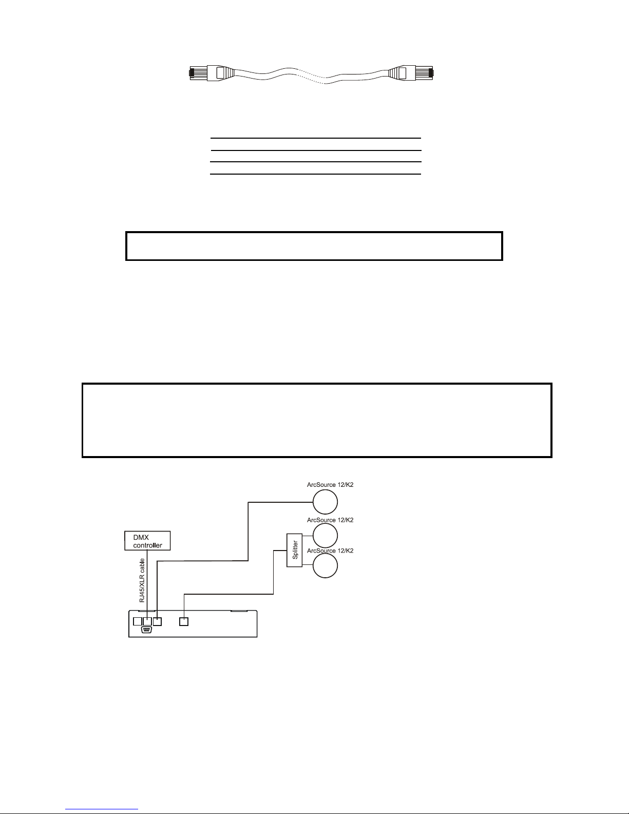
4.3.Conection cables
1.The adapter cable RJ45/XLR connects the ArcPower 72/K2 to the DMX controller.If your DMX controller has
RJ45 socket for DMX output,use RJ45 patch cable for connection with the ArcPower 72/K2.
RJ45 plug DMX 512 XLR plug (male)
View facing pins Front view of the plug
Pin 1: Not used Pin 1: GND
Pin 2: Not used Pin 2: Data -
Pin 3: Not used Pin 3: Data +
Pin 4: Not used Pin 4: Not used
Pin 5: Not used Pin 5: Not used
Pin 6: Data +
Pin 7: Data -
Pin 8: GND
Flat surface
Mounting hole
Screws
Screws
6
2.RJ45 patch cables category 5 that connect the ArcPower 72/K2 each other are wired 1:1,that is,pins with the
same numbers are connected together.
Pin 1: Not used Pin 1: Not used
Pin 2: Not used Pin 2: Not used
Pin 3: Not used Pin 3: Not used
Pin 4: Not used Pin 4: Not used
Pin 5: Not used Pin 5: Not used
Pin 6: Data + Pin 6: Data +
Pin 7: Data - Pin 7: Data -
Pin 8: GND Pin 8: GND
5.Installing instructions.
Never connect 1W LEDs modules to the ArcPower 72/K2
5.1.DMX operating
1.Unplug from the mains before installation.
2.Connect the LED modules to the xture.Make sure that all modules include Luxeon K2 LED´s.
3.Connect the DMX controller to the xture
4.Connect the xture to the mains
5.Set the DMX address on the control board of the xture (see chapter "Control board").
6.Check the current limit setting "C.Li" in menu "SPE" (see chapter "8.6 Special functions").
Warning!
Accidental connection DMX 512 Input/Output to non-DMX 512 device (e.g.Ethernet
network Hub) can damage the ArcPower 72/K2.
Maximum total cable length between one LED zone output of the Arcpower 72/K2
and all its connected LED modules is 40 metres.
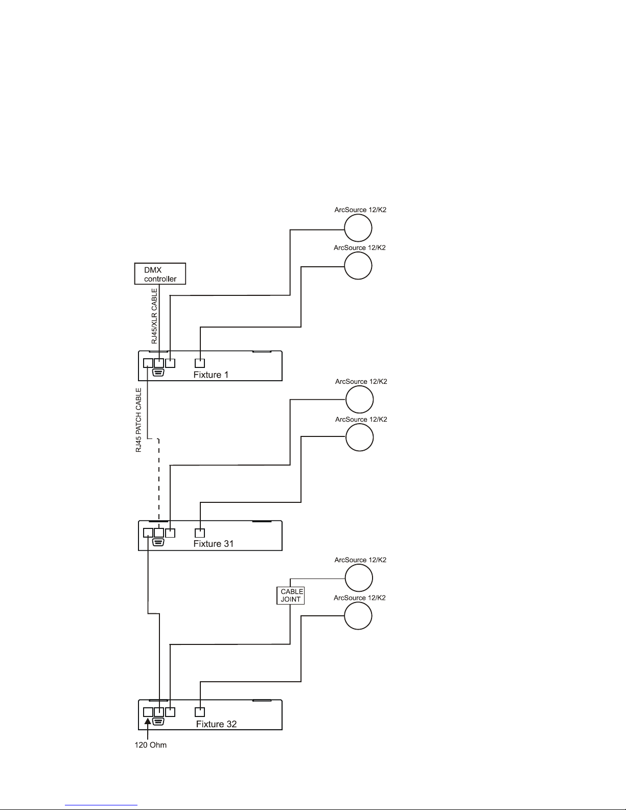
Single ArcPower 72/K2 installation:
7
Multiple ArcPower 72/K2 installation:
Connect the DMX output of the rst ArcPower 72/K2 with the DMX input of the next ArcPower 72/K2. Always
connect one output with the input of the next ArcPower 72/K2 until all xtures are connected.In this way,up to
32 xtures can be chained together.
At the last ArcPower 72/K2 the data link has to be terminated with a terminator. A termination plug is simply a
RJ45 connector with a 120 Ω resistor between pins Data (–) and Data (+).Plug terminator in the DMX output
of the last ArcPower 72/K2.
Maximum number of LEDs connected to the one zone of the ArcPower 72/K2 is 36. in RGB mode and 42 in
RGBW mode.
Note: You cannot combine RGB and RGBW modules (at one LED output) each other as white LEDs
will not light.
8
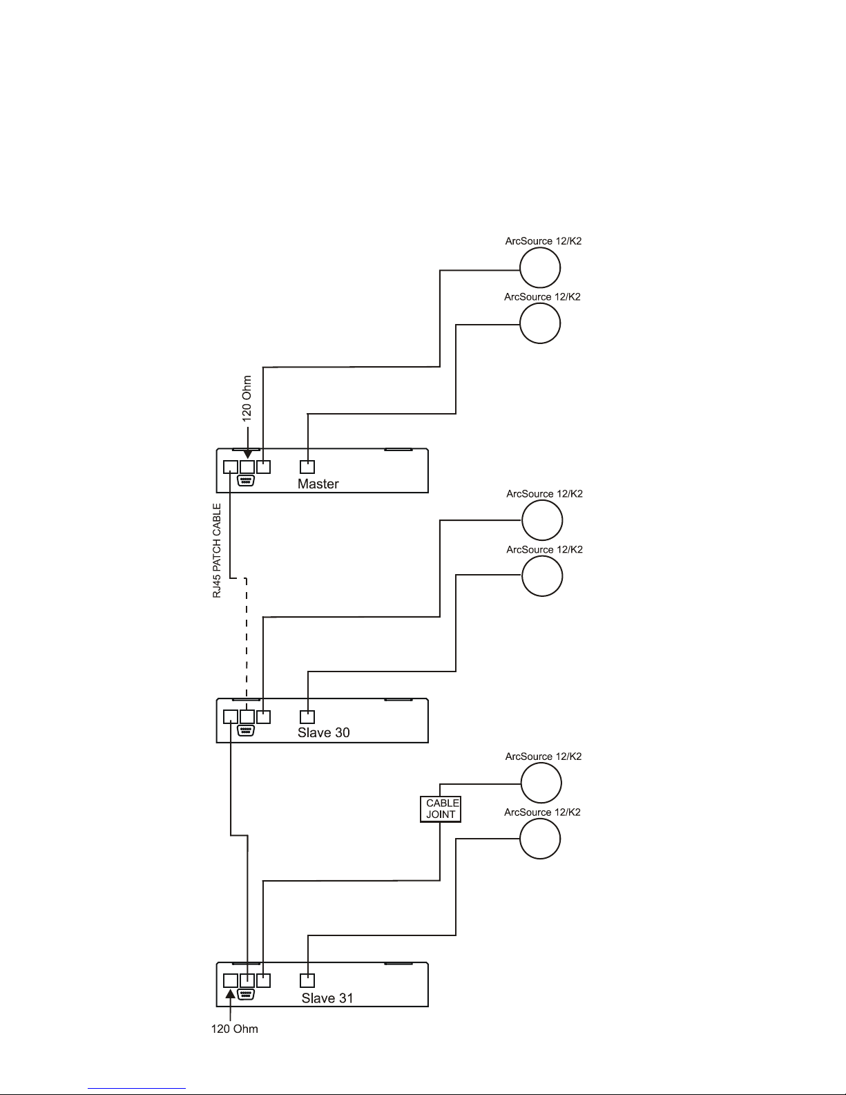
5.2.Master-slave operating
1.Unplug from the mains before installation.
2.Connect the LED modules to the xtures.
3.Connect the DMX output of the master xture in the data-chain with the DMX input of the rst slave. Always
connect output with the input of the next slave until all slaves are connected.Up to 32 xtures can be connected
in master/slave chain
4.Insert the termination plug (with 120 Ohm) into DMX input of the master xture and into the DMX output of
the last slave xture in the link in order to ensure proper transmission on the data link.
5.Connect the xtures to the mains.
6.Check the current limit setting "C.Li" in menu "SPE" (see chapter "8.6 Special functions").
7.See chapter "Stand-alone mode" in order to set the xture as a master or slave.

9
5.3. Operating via DyNet protocol
1.Unplug from the mains before installation.
2.Connect LED modules to the fixtures.
Connect first fixture to the control panel which suports DyNet protocol.
3.Connect the DMX output of the first fixture in a data link with the DMX input of the second fixture. Always
connect output with the input of the next fixture until all fixtures are connected.Up to 32 fixtures can be con-
nected in data chain.
4.Insert the termination plug (with 120 Ohm) into DMX output of the last fixture in order to ensure proper trans-
mission on the data link.
5.Connect fixtures to the mains
6.Select the DyNet protocol on all fixtures (menu SPE"---> Prt---> "dYn").
A description of each byte in the DyNet protocol is the following:
Byte 0: 1C - hexadecimal Logical Message (xed value)
Byte 1: 01 - Area
Byte 2: 00 – Channel level
Byte 3: 80 - Channel
Byte 4: ff – Channel Offset
Byte 5: 00 – Fade Rate
Byte 6: FF (xed value)
Byte 7: 1C Checksum
Area - (0 to 255), as set on the Arcpower to give a unique address for each Arcpower unit (i.e. DMX base
address)
Channel Level - (0 to 255), level - 01=100%, FF=0%
Channel - (80 to 83), 80= channel 1, 81= channel 2, 82= channel 3, 83= channel 4, (see Channel Offset
if more than 4 channels)
Channel Offset - (0-255), default (FF)- channel offset in blocks of 4: (FF = CH 1-4, 00 = CH 5-8,
01 = CH 9-12, etc up to 3E = CH 253-256 )
Fade Rate - (0-255), fade rate with 1 second resolution (0= 0 seconds, 255= 255 seconds)
Checksum - (0-255), checksum Byte - used to ensure the integrity of the packet.
Negative two's compliment of the preceding 7 bytes.
Example 1:
0x1C,0x10,0x00,0x80,0xff,0x05,0xff,0x52
This would control channel 1 (i.e. Red) of Arcpower unit, address 16 to a Level of 100% with a fade of 5
seconds.
Example 2:
0x1C,0x05,0xCC,0x82,0xff,0x0A,0xff,0x52
This would control channel 3 (i.e. Blue) of Arcpower unit, address 5 to a level of 20% with a fade of 10
seconds.
10
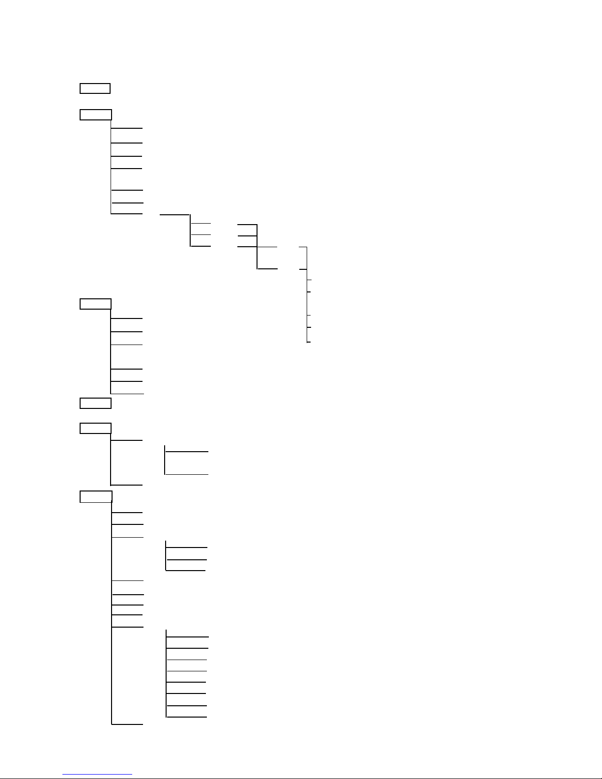
6.ArcPower 72/K2 - Control menu map
Default settings=Bold print
001 (001-502)
PrG
E.P.1
E.P.2
E.P.3
P.01
:
P.06
Aut (OFF,On)
EdI.
E.P.1
E.P.2
E.P.3 S.01
:
S.30
End
rE1 (0-255)
MAn. :
rE1 (0-255) FA.t.(0-255)
Gr1.(0-255) S.tI. (0-255)
bL1.(0-255) COP.
:
MAC. (0-255)
Str. (0-255)
diM. (0-255)
tSt
St.A.
MSt.
E.P.1
:
P06
SLA.
SPE.
VEr.
bAL.(On,OFF)
C.bA.
rE.b. (0-200)
Gr.b. (0-255)
bL.b. (0-215)
Zon (Z.00-Z.08)
d.MP. (Mo.1,Mo.2,Mo.3,Mo.4, Mo.5)
i.bL (On,OFF)
Prt (dMH,dYn)
C.Li.
rE1 (420,700)
Gr1(420,700)
bl1 (420,700)
Wh1 (420,700)
rE2 (420,700)
Gr2(420,700)
bl2 (420,700)
Wh2 (420,700)
UPd.(No,YES)
Table des matières
Autres manuels Anolis Alimentation


