Anatek 6000 Series Manuel utilisateur

Anatek 6000 Series DC Power Supply
TECHNICAL MANUAL
Release 2.0
TM-6000-20
XANTREX TECHNOLOGY INC.
357 Lynn Avenue
North Vancouver, B.C.
CANADA V7J 2C4
(604)984-4268

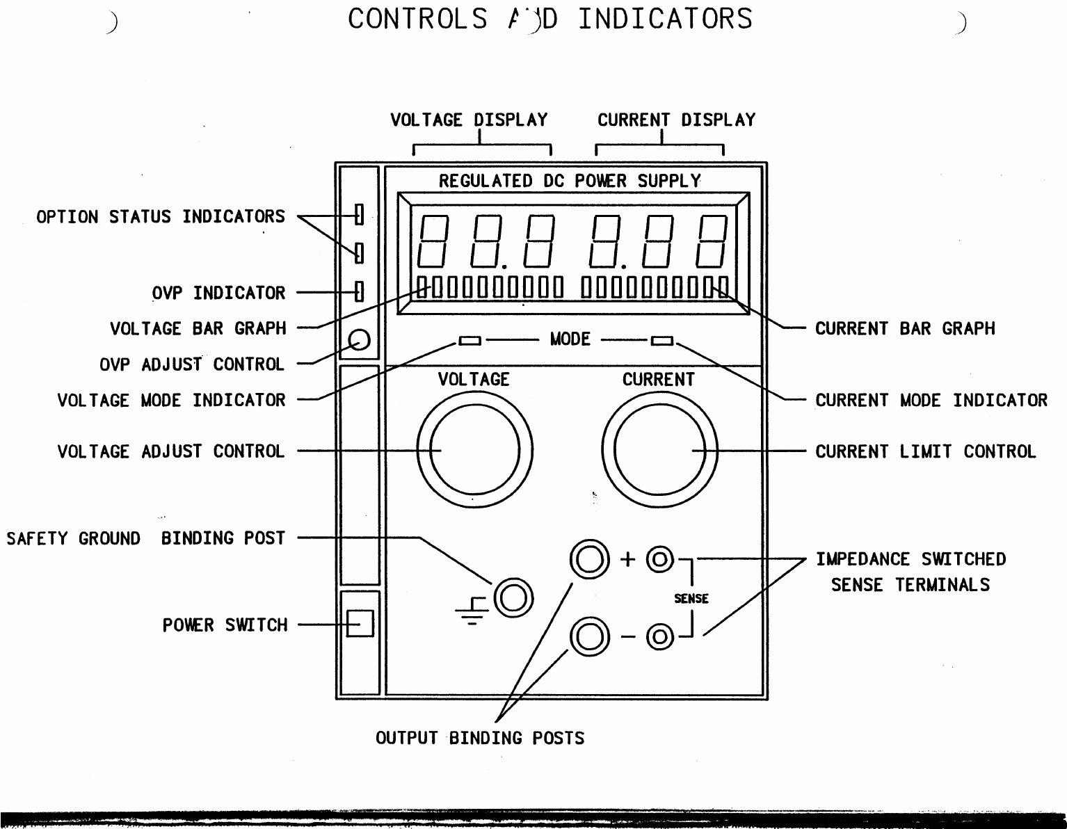
CONTROLS /411) INDICATORS
VOLTAGE DISPLAY
CURRENT DISPLAY
OPTION STATUS INDICATORS
N7;
REGULATED DC POWER SUPPLY
N,
/
Qoo
opp
Nu
—0
,.,
u.
LI 11
100010100
ininiiiiil-iI
N,
/
MODE
t=1
NT
VOLTAGE
CURRE
Oo
SENSE
-
- (>
1
QVP INDICATOR
VOLTAGE BAR GRAPH
OVP ADJUST CONTROL
VOLTAGE MODE INDICATOR
VOLTAGE ADJUST CONTROL
SAFETY GROUND BINDING POST
POWER SWITCH
CURRENT BAR GRAPH
..---CURRENT MODE INDICATOR
CURRENT LIMIT CONTROL
7
IMPEDANCE SWITCHED
SENSE TERMINALS
OUTPUT BINDING POSTS

SECTION 1
FEATURES AND SPECIFICATIONS
1.1 PURPOSE
This manual contains operation and maintenance instructions for
the 6000 Series of high performance laboratory power supplies.
The series consists of six basic models which can be combined
into dual, triple, and quadruple configurations in any
combination of models. The basic models are designated by a 6
prefix, followed by the voltage rating, followed by an S for a
single supply, D for a dual supply, T for a triple supply, or Q
for a quadruple supply. For example, the 6007S model number
signifies that this is a single supply rated at 0 to 7 Vdc
output. Similarly, a 6015D is a dual supply rated at 0 to 15 Vdc
per individual unit.
Five major sections form the manual divisions:
Section 1 - Description of series features and specifications.
Section 2 - Installation and operating instructions.
Section 3 - Theory of operation.
Section 4 - Maintenance and service procedures.
Section 5 - Drawings, schematics, and parts lists.
1.2 DESCRIPTION
The 6000 Series of laboratory power supplies are designed to
provide high stability, continuously variable output voltage and
current for a broad range of development and system requirements.
The 6000 Series employs precision linear regulator technology to
achieve precise regulation and low output noise levels.
1.3 OPERATING MODES
The 6000 Series has two basic operating modes: Constant Voltage
and Constant Current. In the former, the output voltage is
regulated at the front panel selected value, and the output
current varies with the load. In constant current operation, the
output current is regulated at the selected value and the output
voltage varies as a function of the output load.
1.3.1 Automatic Crossover
The automatic crossover system enables the unit to transfer
operating modes as a function of load requirements. If, for
example, the load current attempts to increase above the setting
of the current adjust control, the unit will switch automatically
FEATURES AND SPECIFICATION
1-1
Rev - (1/87)

XANTREX TECHNOLOGY INC.
6000 SERIES MANUAL
from the voltage to the current regulating mode. If the load
requirements are lowered, return to the voltage mode will occur
automatically.
1.3.2 Sense Connections
To compensate for losses in power leads connected to the output,
sense connections are provided beside the output binding posts.
Connecting the positive and negative sense lines to the point
where the metered output voltage is desired will automatically
compensate for the voltage losses in the main power leads
(provided the sum of these losses do not exceed 0.5 volts). With
the voltmeter reading 10.0 volts, for example, and having the
sense lines connected directly to the load, the load voltage will
stay at exactly 10.0 volts regardless of the voltage drops in
the power leads, no matter how much current is drawn. Do not use
the sense connections without the normal power lead connections
to the output terminals, and avoid reversing positive and
negative lead connections.
1.4 EQUIPMENT FEATURES
o
Simultaneous digital display of both voltage and current.
o
Unique analog bar graph displays of both voltage and current
for ease of monitoring transient changes under varying loads.
o
Ten turn potentiometer voltage control allowing high
resolution setting of the output voltage.
o
Current adjust potentiometer allowing current limiting which
is fully adjustable from zero to the rated output.
o
Automatic mode crossover into current or voltage mode.
o
Impedance-switched remote sensing allowing the voltage at the
load to be displayed without switch ambiguity.
o
Optimized output connections: 5-way binding posts on 0.75
inch centers - dual banana plug, with or without safety
ground.
o
Flexible output configuration: Multiple units can be
connected in parallel or series without damage and are short
circuit proof.
o
Modular design allowing easy replacement or repair of plug
connected sub-assemblies.
o
A broad range of optional features:
-
Over Voltage Protection (OVP)
-
External TTL Shutdown
-
Remote Voltage & Current Programming
-
Audible Mode Indication
FEATURES AND SPECIFICATION
1-2
Rev - (1/87)

XANTREX TECHNOLOGY INC.
6000 SERIES MANUAL
-
Rear Access Connector
-
IEEE488 Interface
-
Output Tracking
1.5 SPECIFICATIONS
1.5.1
Electrical Specifications
Output voltage and current ratings for each model (single unit)
are as follows:
Model Number
Voltage
Current
6007
0
- 7V
0
- 6A
6015
0
- 15V
0
- 4A
6020
0
- 20V
0
- 3A
6030
0
- 30V
0
- 2A
6060
0
- 60V
0
- lA
6120
0
- 120V
0
- 0.5A
measured at ambient temperature. Above
to zero at 70
°
C.
30
0
C, derate linearly
Line Regulation (103-125VAC)
Load Regulation
(0-100% Remotely Sensed)
(10-100%)
Noise and Ripple
Temperature Coefficient
(after 30 minutes)
Drift
(Over 8 hrs. after 30 minutes)
Transient Response
(recovery to 0.05% BAND)
+/-50% load change in the range
of 25% to 100% of rated load.
Ambient Operating Range
Storage Temperature
Voltage Mode
Current Mode
0.01% + 2mV
0.01% + 250uA
0.01% + 2mV
0.01% + 250uA
<1mV rms
<2mA rms
0.015%/
0
C
0.02%/
0
C
0.02%
0.03%
<100uSec
0-30
°
C for full rated output.
Derate linearly to zero at
70
°
C.
-55 to +859C

XANTREX TECHNOLOGY INC.
6000 SERIES MANUAL
1.5.2 Mechanical Specifications
Height
Width
Depth
Weight
Single Supply
132mm 109mm
297mm
3.1kg
5.2in
4.3in
11.7in
6.81bs
Dual Supply
132mm
216mm
297mm
6.0kg
5.2in
8.5in
11.71n
13.21bs
Triple Supply
132mm
325mm
297mm
9.0kg
5.2in
12.8in
11.7in
19.81bs
Quad Supply
132mm
436mm
297mm
12.4kg
(rack mountable) 5.2in
17.0in
11.7in
27.21bs
1.6 OPTIONAL ACCESSORIES
The available options for the 6000 Series power supplies are:
Over Voltage Protection (OVP), Remote ON/OFF, Isolated Tracking,
Remote Voltage Programming and/or Current Programming, Audible
Mode Indicator, and IEEE488 Interface.
The quad configuration comes with 19" rack mounting flanges and
may be used rack mounted or free standing. Single, dual and
triple configurations are configured for benchtop use but may be
19" rack mounted using an optional rack mounting adaptor.
Options are available in four different configurations. Option
11 provides overvoltage protection (OVP), remote programming,
remote ON/OFF, and rear panel output terminals. Option 14
provides all of the features in option 11 plus isolated tracking
and audible mode indication. Option 16 includes the IEEE488
interface allowing output voltage and current programming
directly in volts and amperes with 12-bit resolution from
IEEE488/GPIB equipped controllers. Overvoltage protection and
8-bit digital readback of voltage and current are also provided
with this option. Option 15 includes all the option 16 features
except digital readback.
1.6.1 Option Specifications
Over Voltage Protection
Remote ON/OFF
Isolated Tracking
Trip Voltage range: 3.0V to full
output plus 10%.
Minimum setting above output
voltage to avoid false tripping:
4% of output plus 2V.
Standard TTL:
High = 3V minimum, output is OFF
Low = 0.8V maximum, output is ON
Tracking Error:
Fixed ratio of 1% +/-1 count on
each voltage display.
0,111,41TT.TO
,
ISATT,,,V
1 A
(1/071

XANTREX TECHNOLOGY INC.
6000 SERIES
MANUAL
'
-
emote Programming
Programming Voltage Coefficient:
Voltage: 1V/10% of output +/-.1%
Current: 1V/10% of output +/-.1%
Rear Panel Connectors
Option 11 & 14
Option
15 & 16
Programming Resolution
25 pin female D-sub connector
IEEE488
connector and 4 terminal
output barrier strip
IEEE488
Voltage:
+/-
0.03%
Current:
+/-
0.03%
Programming Accuracy
IEEE488
Voltage:
+/-
0.05%
Current:
+/-
0.05%
Readback Accuracy
IEEE488
(Option 16)
Voltage:
+/-
0.5%
Current:
+/-
0.5%
nriAmrippc
Amn qPRCIFICATION
1-5
Rev - (1/87)

SECTION 2
INSTALLATION AND OPERATING INSTRUCTIONS
2.1 GENERAL
After unpacking, an initial inspection should be performed to
ensure that the unit is in good working order. If it is
determined that the unit is damaged, the carrier should be
notified immediately. Repair problems should be directed to your
nearest Allan Crawford Associates representative or to the
Service Department, Xantrex Technology Inc., 357 Lynn Avenue,
North Vancouver, B.C. V7J 2C4, (604) 984-4268.
2.2 INITIAL INSPECTION
The power supply comes complete with an IEC power cord set and
technical manual. The equipment should be inspected for damage as
follows:
a.
Inspect panel and chassis for dents, and other signs of
obvious damage.
b.
Turn front panel controls from stop to stop: Rotation should
be smooth.
c.
Test the action of the power switch. Switching action should
be positive.
d.
If internal damage is suspected, remove the cover and check
the components and printed circuit board for damage.
Reinstall the cover.
2.3 INSTALLATION
Before connecting the unit to an AC outlet, make sure that the
power switch is in the extended (OFF) position and the Voltage
and Current controls are in their fully counter clockwise
positions. The AC line voltage should be 117V 60Hz nominal.
A voltage control mode indicator (green) is located above the
voltage control knob. A current limit mode indicator (red) is
located above the current limit adjust knob. The power supply
outputs are red and black binding posts. The green binding post
is connected to chassis and line ground.
Connect either the (+) or (-) terminal to the ground terminal
depending upon the desired output voltage polarity using a short
wire for this connection. If the output voltage is to be biased
relative to ground, it is recommended that a 0.01uF capacitor of
sufficient voltage rating (200-1000V) be used in place of the
shorting connection. The power supply outputs may be biased by up
to a maximum of +500Vdc with respect to line safety ground.
INSTALLATION & OPERATION
2-1
Rev - (1/87)

XANTREX TECHNOLOGY INC.
6000 SERIES MANUAL
Plug the line cord into a grounded AC outlet. Push the power
switch to turn on the power supply. The red current LED will
light and the display readings will remain zero.
To use the power supply in the Constant Voltage mode, turn the
current control to its extreme clockwise position and set the
voltage control to the desired voltage. To operate the supply in
the Constant Current mode, turn the voltage control 1/2 turn
clockwise and the current control fully counter clockwise.
Connect a shorting lead across the output terminals and set the
desired maximum value of current limit by turning the control
clockwise. Then disconnect the shorting lead from the output
terminals. The power supply will now automatically switch into
the current limiting mode (current regulation) as soon as the
preset current level is reached and will not exceed this level at
any voltage setting. As soon as the supply starts operating in
current mode, the red current mode LED will turn on.
2.4 ELECTRICAL CHECK
2.4.1 Voltage Mode
To check voltage mode operation, proceed as follows:
a.
Rotate VOLTAGE and CURRENT controls fully counter clockwise.
b.
Connect a DC voltmeter, rated better than .5% accuracy, to the
front panel binding posts (+ and -).
c.
Connect the IEC power cord set to the unit, then to an
appropriate power source and set the POWER switch to ON.
d.
Rotate the CURRENT control 1/2 turn clockwise. Slowly rotate
the VOLTAGE control clockwise and observe the digital
displays. The control range should be from zero to maximum
rated output. Compare the test meter with the voltage display
on the left. Observe the bar graph meter to see that it
tracks as the voltage rises and that the voltage mode
indicator light is ON.
e.
Set the POWER switch to OFF.
2.4.2 Current Mode
To check current mode operation, proceed as follows:
a.
Rotate VOLTAGE and CURRENT controls fully counterclockwise.
b.
Rotate the VOLTAGE control 1/2 turn clockwise.
c.
Connect a DC ammeter between the front panel binding posts (+
and -). Select leads of sufficient current carrying capacity
and an ammeter range compatible with the unit's rated current
n n
/1/071

XANTREX TECHNOLOGY INC.
6000 SERIES MANUAL
output. The ammeter should have an accuracy of better than
.5%.
d.
Set the POWER switch to ON.
e.
Rotate the CURRENT control slowly clockwise. The control
range should be from zero to the maximum rated output. Compare
the test meter reading with the reading on the panel current
meter. Also check that the current bar graph display follows
the rise in current and that the current mode indicator light
is ON.
f.
Set the POWER switch to OFF.
2.5 STANDARD OPERATION
Reliable performance of the power supply can be obtained if
certain basic precautions are taken when connecting it for use on
the lab bench or installing it in a system.
To obtain a stable, low noise output, careful attention should be
paid to factors such as conductor ratings, system grounding
techniques, and the particular way the AC input, DC output, and
remote sensing connections are made.
A conductor size that satisfies the current rating requirements
should be used. To overcome impedance and coupling effects,
however, larger gauge wire and short leads are recommended.
2.5.1 Grounding
Proper grounding connections should be made to avoid paths
between separate ground points. To avoid ground loop problems,
there must be only one ground return point in a power system. If
the load is ungrounded, the appropriate output binding post may
be grounded to the green safety ground binding post on the front
of the unit.
2.5.2 Load Connection
Proper connection of distributed loads is an important aspect of
power supply application. A most common mistake is to connect
leads from the power supply to one load and then from that load
to other loads. In this parallel power distribution method,
voltage at each load depends on the current drawn by the other
loads and DC ground loops are developed. Except for low current
applications, this method should not be used.
A preferred way to distribute power is by the
;
radial distribution
method in which power is connected individually to each
load. In the radial method, a single pair of terminals are
designated as the positive and negative distribution terminals.
This pair of terminals may be the power supply output terminals,
the load terminals, or a distinct set of terminals specially
INSTALLATION & OPERATION
2-3
Rev - (1/87)
Ce manuel convient aux modèles suivants
6
Table des matières