AMERICANA ALUMA-VENT Manuel utilisateur
Before You Begin:
Consult your local building department for any required permits
You may be required to obtain a building permit for this structure. Contact your local building department
for details.
Read instructions thoroughly
Please read all instructions and notes carefully prior to assembly. Americana is not responsible for replacing
parts lost or damaged due to incorrect assembly.
A solid attachment is required for all existing structures
All points of attachment to existing structures (such as house, deck, or patio) must be into solid, structurally
sound, and secure material. Example: wood or metal studs, joists, headers, plates, or sills.
Attachment may be made to block, concrete, brick, or stone veneer with suitable anchors, purchased
separately. Note: Failure to properly fasten unit to wall, deck, porch, or patio may result in damage to the
unit, damage to the structure it is attached to, and could cause serious bodily injury.
Check for all parts
Use the Parts and Hardware List to check for any missing parts. To prevent scratching of painted materials,
place on a tarp or other protective material.
Assistance may be required during certain steps of assembly.
CAUTION
Proper site preparation is required.
Standard shade structure design does not include additional loads such as hanging heavy plants,
swings, or other objects.
DO NOT stand or sit on the shade structure roof.
Repair or replace broken parts immediately.
This kit contains parts with metal edges. Please be careful when handling.
Americana Building Products . 110/29/2013
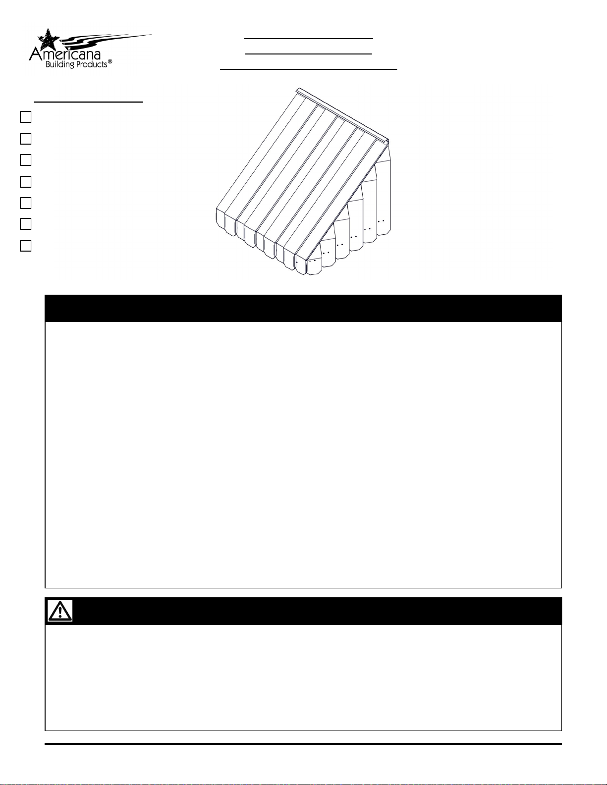
ALUMA-VENT AWNING
REGULAR END STYLE
INSTALLATION INSTRUCTIONS
Contact us at:
1-800-851-0865 or
www.americana.com
Options in your kit:
A. Splice — Pg 16
B. Column — Pg 17
C. C-Channel Brace — Pg 19
D. Runner Brace — Pg 21
E. Kicker Brace — Pg 23
F. Extended Ends — Pg 24
G. Flat Ends — Pg 25
To view installation video,
visit www.americana.com.
Select “Residential Products”.
Select “Installation” at the top
of the page.
Select “Streaming Videos”
then “Aluma Vent Installation.”
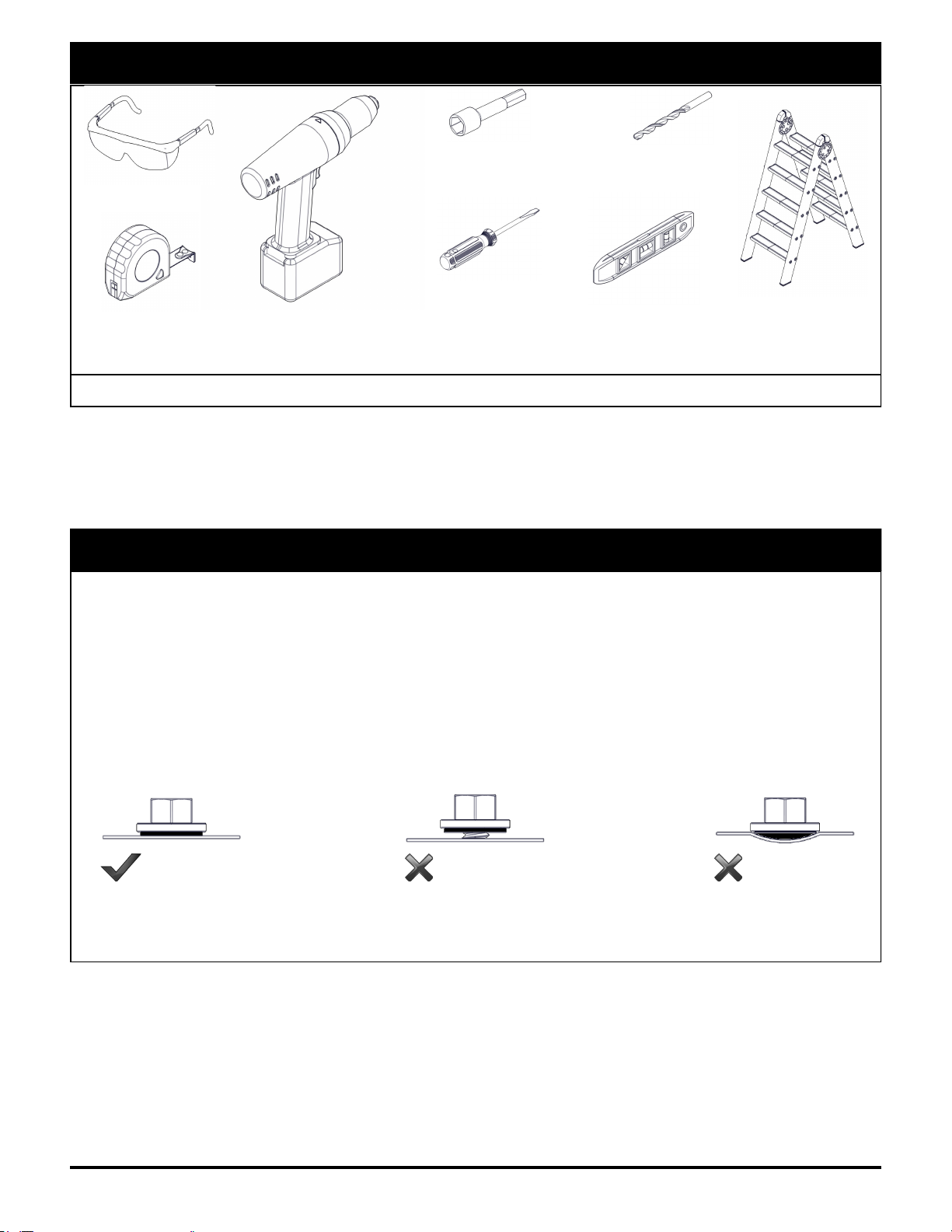
Tools Needed for Installation
Installation Notes and Tips
Complete site preparation before beginning assembly.
DO NOT attempt to assemble on a day with strong winds.
Have assistance nearby to lift and secure parts in place.
It is recommended to lower the speed of electric drills during this installation. Installing Tek screws at
a high RPM may cause the Tek screws to become damaged or break during installation.
Avoid over-driving, under-driving, or driving at an angle to properly install fasteners. Over-driven
fasteners can depress the material and allow water to collect around the fastener, which will corrode
the surface finish. Under-driven fasteners can cause leaks and may back out over time.
We strongly recommend using a high grade sealant, such as our 100% silicone caulk and sealant.
Caulking should be applied uniformly and without skips. A poor caulking job can cause leaks.
Americana Building Products . 210/29/2013
Safety Glasses
Tape Measure Carpenters Level
Electric Drill
Screw Driver
Flat & Phillips Ladder
Socket / Hex Head Driver
Sizes: 1/4”, 11/32”, 3/8” Drill Bit
Sizes: 1/8”, 5/16”
Other Required Tools: Gloves, Chalk Line, Silicone Caulking
Recommended Tools: Rubber Mallet, Carpenters Square, Pliers, Tin Snips
CORRECT TOO LOOSE TOO TIGHT
Note: These are basic installation guidelines for our standard load units and may not be suitable to your
specific installation. It is important to follow all local and national building codes when installing any exterior
improvement product. If you have questions regarding the proper installation of any Americana product, please call
us toll free
Required Parts Not Included In Kit:
Appropriate anchors or lag screws to attach awning to your home’s exterior finish, 3/16” diameter.
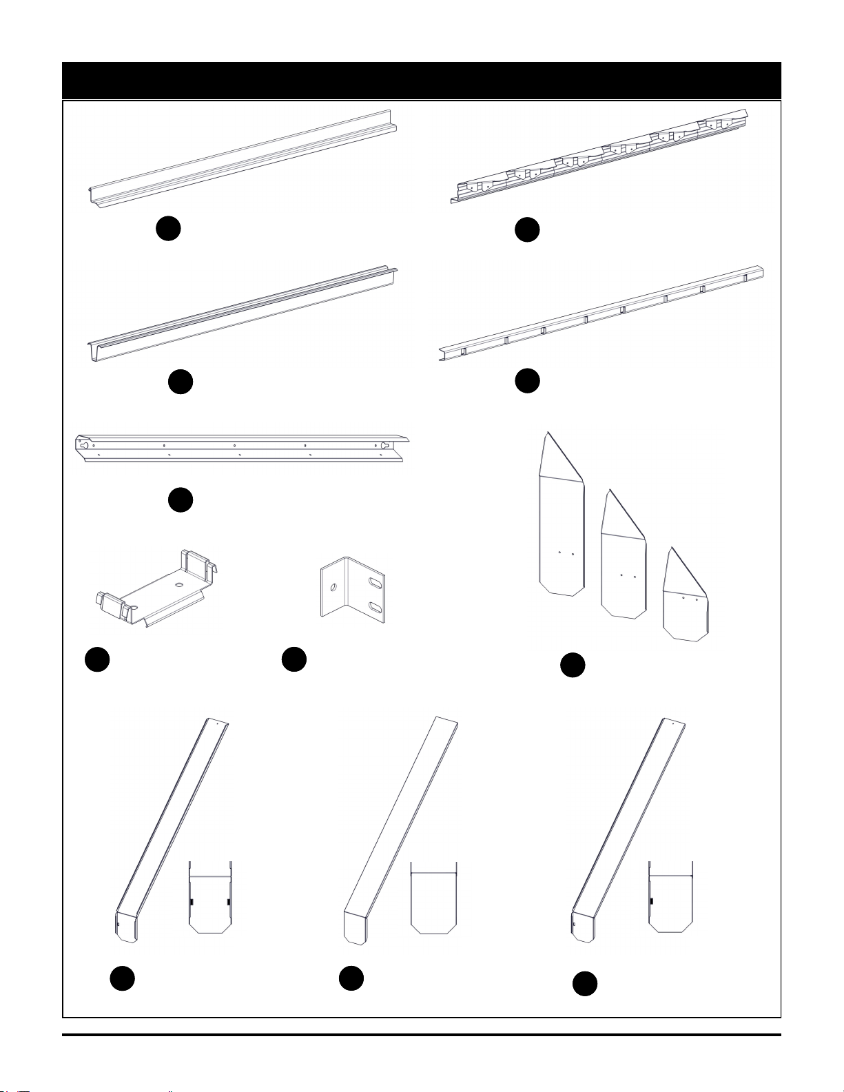
Parts List
NOTE: Length and quantity of parts will vary based on the size of the awning.
Rafter
Part Code: 60506
ASawtooth
Part Code: 60507
B
Runner
Part Code: 10459-C
CApron Bar
Part Code: 60502
D
Flashing
Part Code: 10459-E
E
Louvers
Part Code: 10417-H
H
Bottom Pan
Part Code: 10417-I
ITop Pan
Part Code: 10417-J
JEnd Pan (RH Shown)
Part Code: 10417-K
K
Clip
Part Code: 60505
FWall Bracket
Part Code: 60504
G
Americana Building Products . 3Aluma-Vent Installation Guide
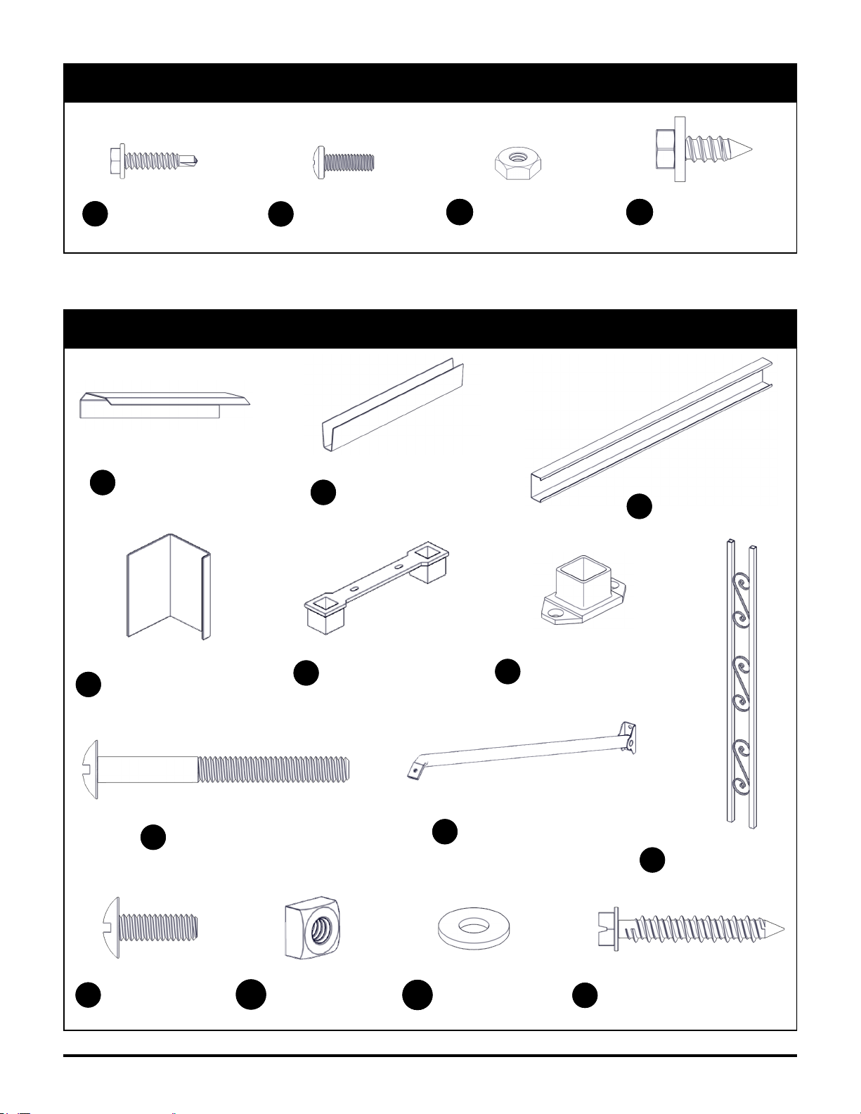
Hardware List
#8 x 3/4” Screw
Part Code: 20121
AA #8 x 1/2” Bolt
Part Code: 20754
BB #8 Hex Nut
Part Code: 20502
CC
Screws shown actual size.
Americana Building Products . 4Aluma-Vent Installation Guide
#14 x 3/4” Screw
Part Code: 20792
DD
Optional Coordinating Parts and Hardware
NOTE: Length and quantity of parts will vary based on the size of the awning.
Flashing Splice
Part Code: 10459-L
LRunner Splice
Part Code: 60515
M
Column
Part Code: 60722
R
Upper Column Bracket
Part Code: 90442
PColumn Mounting Bracket
Part Code: 50131
Q
C-Channel Brace
Part Code: 30151-N
N
C-Channel Wall Bracket
Part Code: 30151-O
O
1/4” x 2-1/2” Bolt
Part Code: 20406
EE
1/4” x 3/4” Bolt
Part Code: 20751
FF 1/4” Square Nut
Part Code: 20503
GG 1/4” Flat Washer
Part Code: 20902
HH 1/4” x 1-3/4” Tapcon Anchor
Part Code: 20794
II
Kicker Brace
Part Code: 6081X
(varies by length)
S
Americana Building Products . 5Aluma-Vent Installation Guide
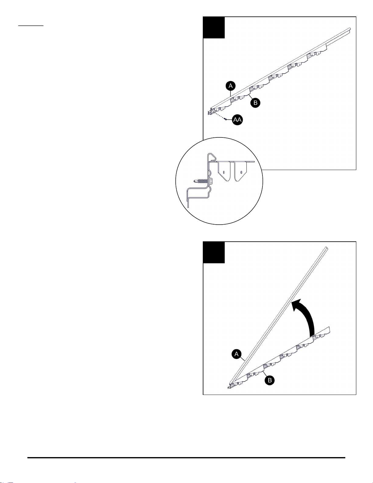
STEP 1
In some cases, rafter (A) and sawtooth (B) are not
pre-assembled. If this happens, position rafter (A)
so the curl rests on top of sawtooth (B) and the front
ends are flush. Attach using a #8 x 3/4” screw (AA)
through the pre-drilled hole in sawtooth (B).
Open the right-hand rafter (A) and sawtooth (B)
assembly to approximately the desired slope of the
awning.
1A
1B
FRONT VIEW
Americana Building Products . 6Aluma-Vent Installation Guide
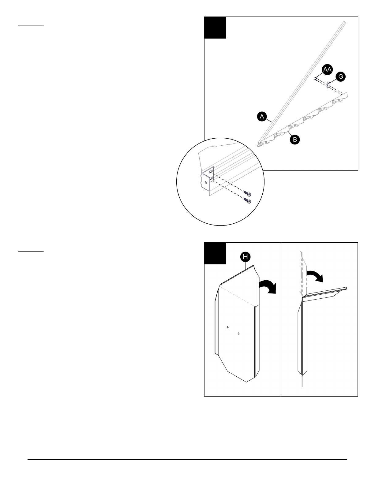
STEP 2
Attach wall bracket (G) to sawtooth (B) using (2) #8
x 3/4” screws (AA) through the pre-drilled holes.
DO NOT completely tighten screws at this time.
NOTE: If you ordered the optional flat style louver
ends, see Optional Sheet G.
STEP 3
Select the right-hand set of louvers (H). Lay each
one on a flat surface and make a horizontal bend
even with the notch at the top end. Bend at
approximately a 90 degree angle, and then bend
back to approximately a 45 degree angle.
2
3
Americana Building Products . 7Aluma-Vent Installation Guide
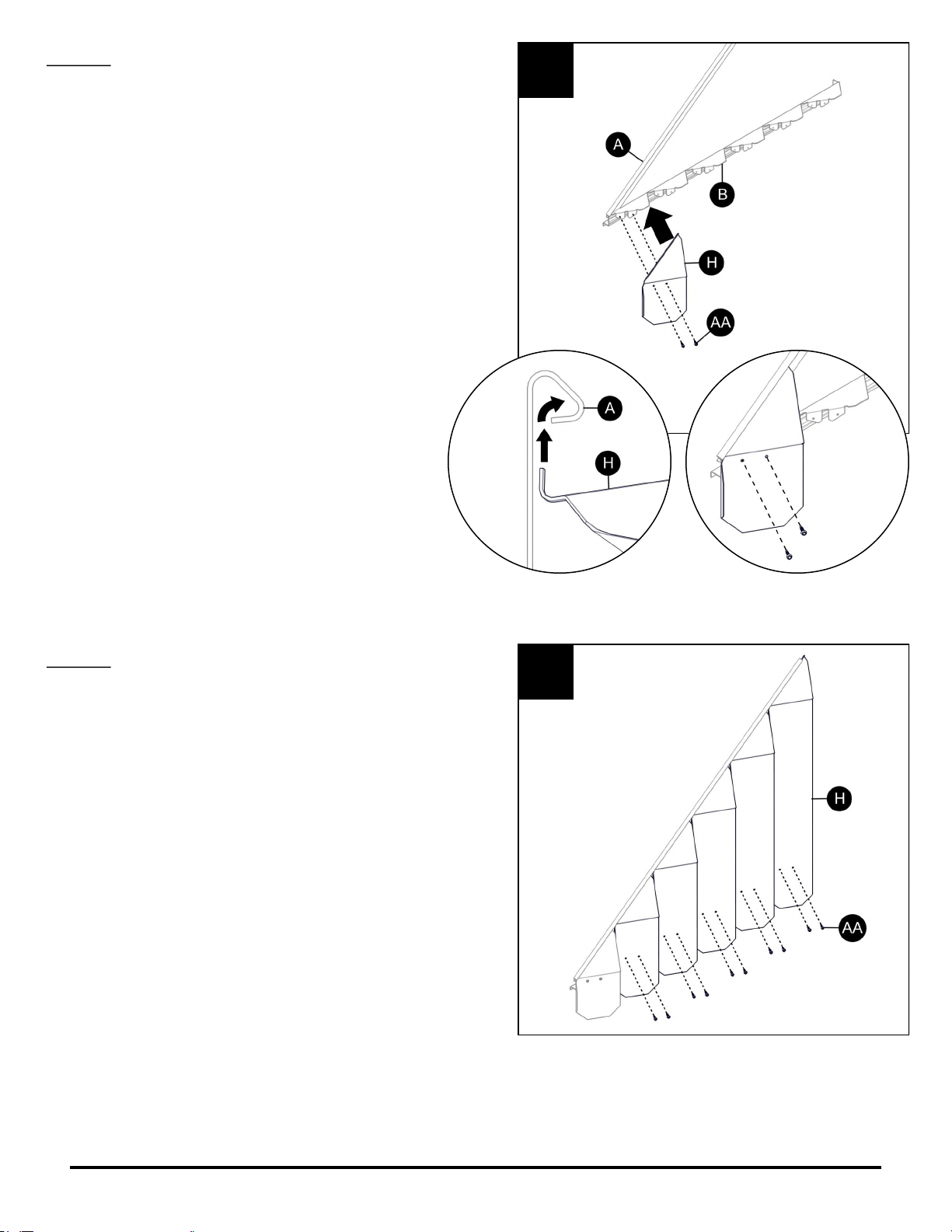
STEP 4
Insert the curl of the shortest louver (H) into the
curled channel of rafter (A) over the first tab from
the front on sawtooth (B).
Align the holes in louver (H) with the holes in
sawtooth (B) by raising or lowering rafter (A).
If necessary, also change the bend on louver (H).
Attach using (2) #8 x 3/4” screws (AA).
TIP: Install screw (AA) in the back hole of louver (H)
first, then use the leverage of sawtooth (B) and
rafter (A) to align the front hole.
STEP 5
Repeat step 4 to complete the right end louver
assembly, beginning with the longest louver (H) and
working down.
On awnings with extended ends, begin with the
louver closest to the back end of rafter (A). Sawtooth
(B) will have extra tabs for the extension louvers. Be
sure not to attach the last louver to an extension tab.
NOTE: If you ordered extended louver ends, see
Optional Sheet F.
4
5
FRONT VIEW
Americana Building Products . 8Aluma-Vent Installation Guide
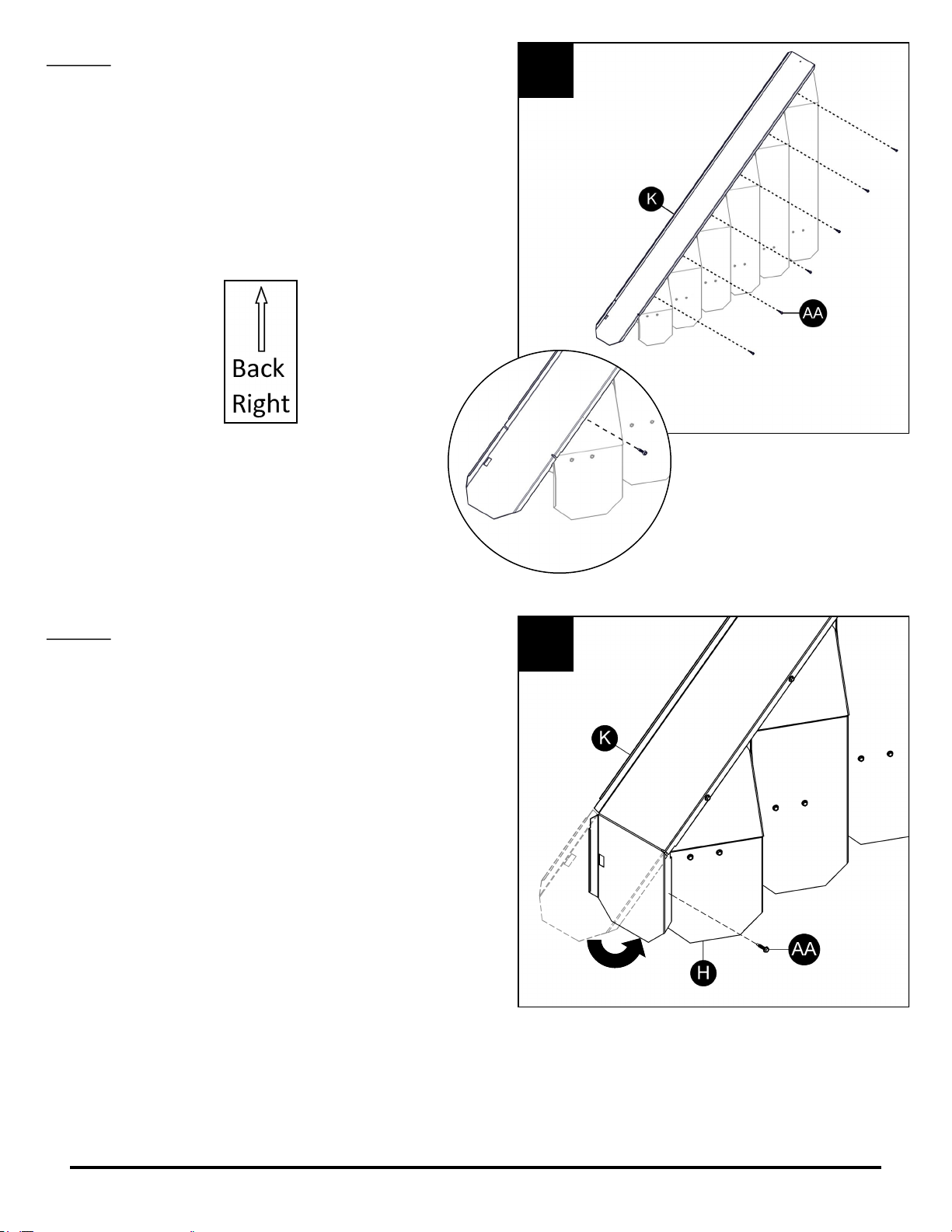
STEP 6
Select the right-hand end pan (K) by checking the
sticker at the top of the pan. Attach to the right-hand
louver (H) assembly using #8 x 3/4” screws (AA).
Line up the pre-drilled holes in end pan (K) with the
pre-drilled holes in rafter (A).
STEP 7
Bend the valance of end pan (K) and attach to
louver (H) using #8 x 3/4” screws (AA) through the
pre-drilled holes.
This completes the right-hand end assembly.
Repeat steps 1-7 to complete the left-hand end
assembly.
6
7
Look for
sticker at
top of pan.
Americana Building Products . 9Aluma-Vent Installation Guide
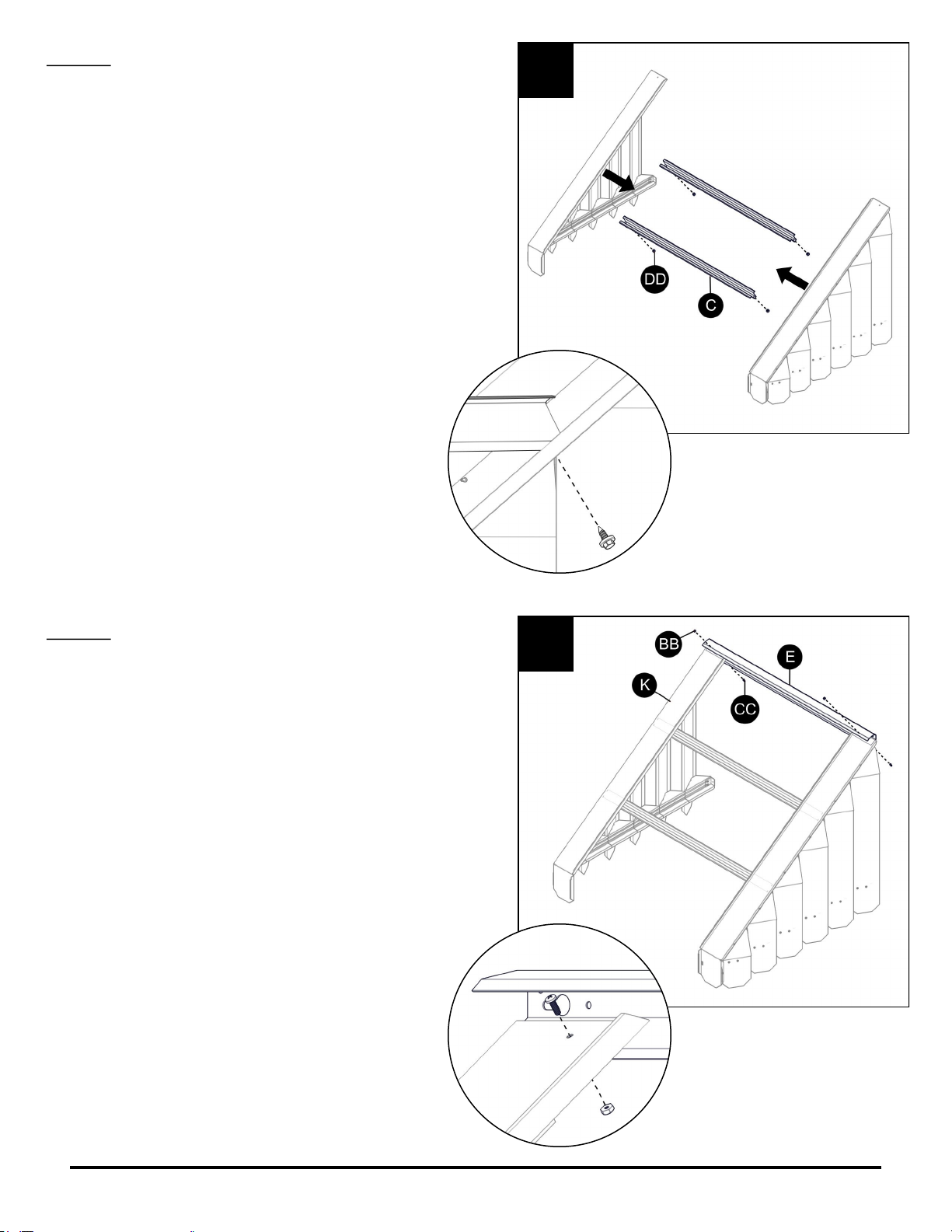
STEP 8
Attach runners (C) to the left- and right-hand end
assemblies using #14 x 3/4” screws (DD) through
the pre-drilled holes in rafter (A).
STEP 9
Select flashing (E) and attach to end pans (K) using
#8 x 1/2” bolt (BB) and #8 hex nut (CC) through the
pre-drilled holes.
8
9
Americana Building Products . 10 Aluma-Vent Installation Guide
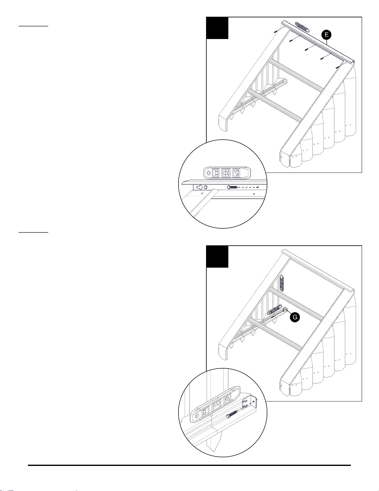
STEP 10
At this point, the awning may be lifted up and
attached to the mounting surface. Anchors are not
supplied with this kit. 3/16” diameter anchors
suitable for your mounting surface are required.
NOTE: Awning must be attached to a solid
structural support. DO NOT attach awning to
sheathing, siding, flashing, or any other
non-structural surface.
While using a level to keep flashing (E) plumb,
attach to the mounting surface through the
pre-drilled holes. Pre-drill a pilot hole into the
mounting surface using a 1/8” drill bit before
attaching anchors.
STEP 11
With only the top of the awning attached to the
mounting surface, use a level to plumb sawtooth (B)
and louvers (H). Looking at the side of the awning,
the louvers should be parallel to the mounting
surface. Looking at the front of the awning, the
louvers should appear straight up and down.
With the awning properly aligned, attach mounting
bracket (G) to the mounting surface using 3/16”
diameter anchor, purchased separately. Then be
sure to tighten the #8 x 3/4” screws (AA) attached to
mounting bracket (G). Pre-drill a pilot hole into the
mounting surface using a 1/8” drill bit before
attaching anchors.
TIP: Align and attach one end of the awning
before moving to the other side to avoid either
side falling out of alignment.
Once the awning is attached, if you need to
move runner (C) to avoid an out-swinging door
or window, remove #14 x 3/4” screws (DD),
re-position the runner, then re-attach screws.
10
11
Table des matières
Autres manuels AMERICANA Accessoires


