American Flyer Defender Set Manuel utilisateur

American Flyer
Defender Set
Owner’s Manual
74-9624-250
3/13
CAUTION: Use only the projectiles included with this product. Do not
aim the projectile and launching mechanism at any person. Adult
supervision is recommended.
CAUTION: The coil on the flatcar deck may reach high temperatures.
Do not touch the coil until cool.

2
C
ongratulations on your purchase of the American Flyer Defender Set. The set you have
always wanted, beautifully recreated. From the sleek little bell ringer C&O GP-7 to the
Rocket Launcher and Searchlight Cars, this set has all the makings of childhood memories
with the features you’ve come to expect. Roll down the rails with this set and keep your
railroad empire safe from intruders with ‘The Defender’.
First cataloged in 1959, this American Flyer favorite has been brought back for everyone to
enjoy today! Similar to the original, the set includes GP-7 diesel with ringing bell, Navy flatcar
with vehicles, searchlight car, Marines boxcar, rocket launcher, and caboose
Congratulations!
Features of this locomotive
Rolling stock features:
• Transformer controlled forward, neutral, and reverse operation
• Powerful maintenance-free motor
• Ringing bell
• Directional lighting, including operating headlight and back-up light
• Interior cab light
• Front and rear operating couplers
• Traction tires
• Metal frame
• Die-cast metal trucks
• Die-cast metal trucks with operating couplers
• Illuminated searchlight on searchlight car
• Removable vehicles on Navy flatcar
• Removable rocket on rocket launcher car
• Metal frame and opening doors with latches on boxcar
• Interior illumination in caboose

3
Table of contents
Transformer operations
Running your locomotive with a Lionel transformer 4
Locking your locomotive into a single operational state 5
Turning off the bell sounds. 5
Operating your train set
Using your locomotive's couplers 6
Installing the control rail 6
Unloading the boxcar 7
Placing the automobiles on the flatcar 7
Launching the missile 8
Maintaining and servicing your locomotive
Lubricating your locomotive 9-10
Replacing your locomotive’s lamps 10
Replacing the searchlight car lamps 11
Replacing the caboose lamp 11
Limited Warranty/Lionel Service 12
The following Lionel marks are used throughout this Owner’s Manual and are protected under
law. All rights reserved.
Lionel®, LEGACY™, FasTrack™,TrainMaster®, Odyssey®, RailSounds®, CrewTalk™, TowerCom™,
DynaChuff™, StationSounds™, Pullmor®, ElectroCoupler™, Magne-Traction®, CAB-1®Remote
Controller, American Flyer®, Lionel ZW®, ZW®, MagniVision®, TMCC®, Lionelville®, Wireless
Tether™, Powerhouse™, LionMaster®, Conventional Classics™, Postwar Celebration Series™,
TruRail™, PH-1 Powerhouse®, Powermaster®, Powerstation-Powerhouse®, Accessory Motor
Controller™, AMC™, Accessory Switch Controller™, ASC™, Action Recorder Controller™, ARC™, Track
Power Controller 300™, TPC 300™, Track Power Controller 400™, TPC 400™, Block Power
Controller™, BPC™, Operating Track Controller™, OTC™, FatBoy™, Lionel Lines®, Joshua Lionel
Cowen Series™, Lockon®, TrainSounds™, MultiHorn™, MultiWhistle™, Choo-Choo™

4
3Move ‘em out!
Get your trainset moving. Press the DIRECTION button on your transformer.
This sequences the reverse unit to the next operating state.
Adjust track voltage until your locomotive moves at your desired speed. To
increase speed, increase track voltage. To decrease speed, reduce voltage. To stop the
locomotive, turn-off track power.
See page 5 for information on locking your locomotive into a single
operational state.
Place your train set on American Flyer or S gauge
two-rail track.
The curves must have a radius of at least 20”.
2Power up your locomotive with your transformer.
Your locomotive is designed to operate on 9-15 volts alternating
current. Virtually all American Flyer or Lionel alternating-current transformers
are suitable.
Do not power your locomotive with direct current (DC).
Damage to sensitive electronic components may occur.
1
Running your locomotive with a Lionel transformer
Transformer operations
Caution!
Note!
It is imperative that you keep the powered truck liberally lubricated for reliable
operation. See page 9-10 for more information.
Important!

To select a single operational state for your locomotive (example: forward only), you can
deactivate the reverse unit’s sequencing function with the directional control switch.
Get your locomotive moving in the desired direction, then slow it down without stopping.
Set the directional control switch to OFF. Refer to Figure 1 for the location of the switch. The
locomotive is now “locked” into your chosen direction.
When you no longer want single-direction operation, just slide the switch back to ON.
Your locomotive’s reverse unit will “reset” to forward after any five second or longer
power interruption, regardless of the original locked-out direction.
Slide the sound switch to the OFF position to turn off the bell sounds.
Locking your locomotive into a single operational state
Turning off the bell sounds
Transformer operations
5
Note!
Figure 1. Switch location
Reverse unit
locking switch
Sound switch

6
Operating your train set
Push up on the uncoupling weight located directly under the coupler to open the coupler.
To couple two cars together, place them on the track with at least one of the couplers open,
then slide them together. The couplers will close automatically.
Using your locomotive’s couplers
POWER
SUPPLY
UA
1. As illustrated in Figure 2, snap the control rail onto the track. The two arms snap onto the
underside of the ties.
2. Attach a wire to the
terminal on the control
rail and connect it to a
terminal on the other
separate switch. Refer to
Figure 3.
3. Attach a wire to the
remaining switch terminal
and connect it to the
Common/Ground U
terminal on the power
supply.
Installing the control rail
Control rail
Control rail arm
Control rail
spring clip
Switch
terminals
Sliding
contact
Figure 2. Control rail attachment
Figure 3. Control rail power connections
7
Operating your train set
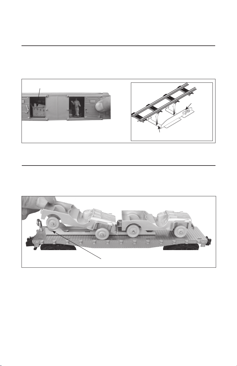
To unload the car, be sure that the power contact is in position on the power rail. Press the button
on the controller, and the door will open and package will be pushed out of the car. Press the
button repeatedly until all packages are unloaded. Reload the packages on the ramp inside the car.
Unloading the boxcar
Control rail
Place packages on ramp
Control rail arm
Figure 4. Unloading the boxcar
Placing the automobiles on the flatcar
Place the automobiles on the flatcar as shown in Figure 5. Place the axles into the slots on the
holder.
Slot
Figure 5. Place the autombiles on the flatcar

8
Launching the missile
To launch the missile, press the rocket down into the base until the mechanism clicks. Position the
power contact on the power rail (see Figure 6), and then press the button on the controller
momentarily to fire. To avoid damage to the car, do not hold the button down for more than 10
seconds with the car in place on the control rail.
Keep clear of the missle and launch mechanism.
The coil on the flatcar deck may reach high temperatures. Do not touch the coil
until cool.
Caution!
Caution!
Control rail
Control rail arm
Power contract
Hot surface!
Do not touch!
Coil
Figure 6. Launching the missile
Operating your train set
Do NOT press the button on
the controller for more than
10 seconds at a time.

9
Maintaining and servicing your train set
Lubricating your locomotive
H
elp your American Flyer locomotive lead a long and productive life on your railroad by
maintaining it properly.
It is imperative that you keep the powered truck liberally lubricated for reliable
operation.
We recommend that you purchase a Lionel Lubrication and Maintenance Kit (no. 6-62927),
available from your Lionel dealer. Avoid getting grease or oil on the locomotive’s wheels or your track.
You’ll know your locomotive requires lubrication when visual inspection reveals dryness on the parts
indicated in Figure 7 and 8. Remove accumulated dirt and dust before lubricating, and always
lubricate any locomotive emerging from prolonged storage.
Figure 7. Underside details and lubrication points
ON OFF
Body screw
(under truck)
Body screw
(under truck)
Lubricate axles
with Lionel oil
sparingly
on both sides
Lubricate gears
with Lionel
grease
sparingly
Lubricate axles
with Lionel oil
sparingly
on both sides
Body screw
(under truck)
Important!
Lubricating your locomotive (continued)
Replacing your locomotive’s lamps
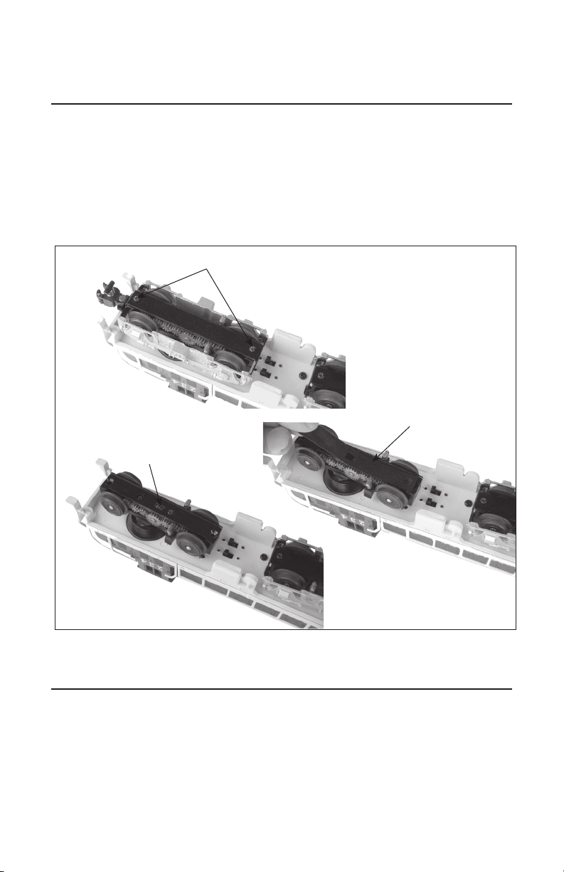
In addition to oiling all axles and the idler gears on the sides of the powered truck (as shown
on in Figure 7 page 9), it is imperative that you lubricate the worm gear with a liberal
amount of Lionel oil (not grease) for optimal performance. To access the square slot on the
underside of the powered truck, remove the two screws from the underside of the bottom plate,
and lift it away, along with the side frame. Refer to Figure 8. Lubricate the gear through the
rectangular slot using Lionel oil, then replace the bottom plate, ensuring that the rubber
gasket is in place.
The headlamps are secured in the number board/headlight lens inside the cab. To replace a lamp,
remove the four chassis screws from the underside of the frame (see Figure 7 on page 9) and
gently lift off the cab. Locate the expired lamp and gently pull it out of the socket. Replace it with
Lionel part no. 6008352311. To reassemble, reverse the procedure.
Maintaining and servicing your train set
10
Figure 8. Truck lubrication
Screws
Worm gear in
rectangular slot
Rubber gasket
Table des matières
Autres manuels American Flyer Jouet


