AmazonBasics B089R7J1CQ Manuel utilisateur

3-Inch Bathroom Exhaust Fan, 70 CFM, 2 Sone, White
3-Ventilateur d’Évacuation d’Air de 11 Pouces pour Salle de Bains,
70 CFM, 2 Sones, Blanc
3-Extractor de Baño de 11 Pulgadas, 70 CFM, 2 Sones, Blanco
B089R7J1CQ

English ..................................... 3
Español .................................... 16
Français ................................... 29

Welcome Guide •English
Part List
Parts Description Qty
AFan Housing x1
Bx1
C
D
E
x1
Grille
Quick Connect Wire Connector x3
Wood Screw (M4x30 mm) x4
Duct Connector
B
A
C
D
E
Contents:
Before getting started, ensure the package contains the following components:
When using in existing construction, for proper installation it is
recommended that you have attic access or access above the installation
location.
Recommended Tools and Supplies: Recommended Fittings:
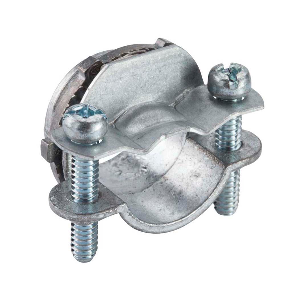
• 3/8 in. Trade Size with 1/2 in. Knockout
Wire Clamp
• Phillips Screwdriver
• Safety Glasses
• Utility Knife/Drywall Saw
• Duct Tape or Clamps
• Hammer (Optional)
• Drill (Optional)
• Drill Bits (Optional)
NOTICE
3

IMPORTANT SAFEGUARDS
Read these instructions carefully and retain them for future use. If this
product is passed to a third party, then these instructions must be included.
PLEASE READ AND UNDERSTAND THIS ENTIRE MANUAL
BEFORE ATTEMPTING TO ASSEMBLE, OPERATE, OR INSTALL
THE PRODUCT.
SAFETY INFORMATION
Always disconnect the power supply prior to servicing the fan, motor, or junction box.
Follow all local building, safety, and electrical codes as well as NEC (National Electrical
Code) and OSHA (Occupational Safety and Health Act).
•
•
Electric Service supply must be 120 volts, 60 hertz.
•This product must properly connect to the grounding conductor of the supply circuit.
•Do not bend or kink the power wires.
•Do not use this fan with any solid state control device, such as a remote control,
dimmer switch, or certain timers. Mechanical timers are not solid state devices.
•
Do not install in a ceiling with insulation greater than R40.
•
TO REDUCE THE RISK OF FIRE, ELECTRIC SHOCK, OR INJURY
TO PERSONS, OBSERVE THE FOLLOWING:
Duct work should be installed in a straight line with minimal bends.
Use this unit in the manner intended by the manufacturer. If you have
any questions. Please call customer service.
•Duct work size must be the same size as the exhaust flange and should not be reduced.
Reducing the duct size may increase fan noise.
•
If this unit is to be installed over a tub or shower, it must be marked as a appropriate
for the application. When the fan is going to install in the bathroom, the fan and the
tub need to be more than 1.0 meter between each other, the fan required to install
at the other side of the tub in ceiling. Acceptable for use over a bathtub or shower
when installed in a GFCI protected branch circuit.
•
WARNING
Before servicing or cleaning unit, switch power off at service panel
and lock the service disconnecting means to prevent power from
being switched on accidentally. When the service disconnecting
means cannot be locked, securely fasten a prominent warning device,
such as a tag, to the service panel.
WARNING
Installation work and electrical wiring must be done by a qualified
person(s) in accordance with all applicable codes and standards,
including fire-rated construction.
WARNING
When cutting the ceiling, do not damage electrical wiring and other
hidden utilities.
WARNING
Ducted fans must always be vented to the outdoors.
WARNING
Sufficient air is needed for proper combustion and exhausting of
gases through the flue (chimney) of fuel burning equipment to prevent
backdrafting. Follow the heating equipment manufacturer’s guideline
and safety standards such as those published by the National Fire
Protection Association (NFPA), and the American Society for Heating,
Refrigeration and Air Conditioning Engineers (ASHRAE) and local code
authorities.
WARNING
4

Before First Use
•Check for transport damage.
Risk of suffocation! Keep any packaging materials away from children
– these materials are a potential source of danger, e.g. suffocation.
DANGER
Airflow: 70 CFM Power Consumption: 25W
Gross Weight: 6.42 lbs.
Ceiling Opening: 7.3 in. (L) x 7.5 in. (W)
Duct Output: 3" Required
Electric Service: 120V, 60Hz
Duct Diameter: 3 in.
Sound Output: 2.0 Sone
Specifications
•
Ensure ducting from fan to the outside of structure uses the shortest and straightest
route for best performance. Not doing so can restrict air flow and increase noise and
energy usage. Never reduce the recommended ductwork size. Fans using existing
ducting may not achieve full air flow ratings.
•
Ensure to follow the “Not Recommended” examples above when installing duct work to
ensure proper ventilation.
•Ensure duct joints and exterior penetrations are sealed with caulk or other similar
material to create an air-tight path and to minimize structure heat loss and gain and
reduce the potential for condensation.
•
Wrapping duct with insulation can minimize possible condensation buildup, heat loss,
heat gain and inhibit mold growth.
Typical Installation
Fan housing
Duct
Roof cap
Eave vent
Wall cap
Eave
Roof
Wall
Fan housing
Duct
Too sharp of bend
Fan
body
Minimum 18"
Avoid duct shrink
Too many bends
Elbow near the body
RECOMMENDED
Not Recommended
Typical Installation
Duct
Fan housing
Fan
Housing
Minimum 18"
Not Recommended
5

• Strip all wires so 3/8 in. – 1/2 in. of the copper wire is exposed.
• Firmly grip wire and insert stripped end of wire into open port of quick connect wire
connector. Only insert one wire per port. Wires should only be inserted into quick
connect wire connectors that have same color wire covering.
• Ensure stripped end of wires are tight and fully inserted to back of connector.
Pre-Installation
WIRING DIAGRAMS
Quick Connect Wire Connectors INSTRUCTIONS
To be sold only with installation instructions.
HOUSE WIRES
PRODUCT WIRES
QUICK CONNECT
WIRE CONNECTOR
Wiring must comply with all applicable electrical codes. Turn OFF
power at the service panel before removing or installing connectors.
WARNING
COPPER TO COPPER ONLY. Do not use Aluminum wire.
Quick Connect Wire Connectors installation should follow the
instructions below.
Quick Connect Wire Connectors are reusable on solid wires of the
same wire gage or smaller. Do not reuse the connector on stranded
wires.
WARNING
CAUTION
NOTICE
The acceptable solid wire range is 12-18 AWG.
NOTICE
QUICK CONNECT
WIRE CONNECTOR
PRODUCT
WIRES
HOUSE
WIRES
TO SWITCH
TO NEUTRAL
TO GROUND
Junction box
FAN HOUSING
Green wire
MOTOR
CAPACITOR FOR
LONG LIFE OF
MOTOR
Automatic terminal switch
Black wire
White wire
6

• Place the fan housing (A) next to a celling
joist.The fan housing should be level and
perpendicular to the joist.
Installation - New Construction
Step 1: Fan housing placement
Make sure power is switched off at service panel before starting installation.
CAUTION
Unit is designed for ceiling installation only.
NOTICE
A
1
2 4 6 8 10 12 14
16 18 20
35791113
151719
O
N
O
N
O
F
F
O
F
F
O
N
O
F
F
O
N
O
N
O
F
F
O
N
O
F
F
O
N
O
F
F
O
N
O
F
F
O
N
O
F
F
O
N
O
F
F
O
N
O
F
F
O
N
O
F
F
O
F
F
O
N
O
F
F
O
N
O
F
F
O
N
O
F
F
O
N
O
F
F
O
N
O
F
F
O
N
O
F
F
O
N
O
F
F
CEILING JOIST
• Carefully remove the unit from the carton.
• Inspect duct work and wiring before proceeding with installation.
• You may need the help of a second person to install this fan. One person on the attic
side and one on the room side.
• Ensure area above installation location is clear for proper wiring and duct work for
fan installation and future maintenance.
Pre-Installation
Before installing product, make sure all parts are included. Compare parts with parts list
contents on page 3. If any parts were not included or damaged, do not attempt to install
the product.
Turn off electricity at the service panel before beginning installation.
WARNING
Replacement fan installations may vary due to how previous fans were
installed. Tools and supplies needed for proper installation are not
included but can be found at home improvement and hardware stores.
NOTICE
7

• Mount the fan housing (A) to the joist
using wood screws (E) where indicated.
•
Installation - New Construction
Step 2: Mount the fan housing
Step 3: Connect house and fan wires
White
White
D
Black
Black
D
Green/Copper
Green/Copper
D
FIG 1
FIG 2
E
E
A
CEILING JOIST
Remove screw from junction box cover and
remove cover from junction box on
the fan housing. Note how flange on bottom
of cover is positioned (FIG 1).
It is recommended to use a
3/8 in. trade size with 1/2 in. knockout wire
clamp to secure wiring to junction box cover.
Black/red wires are typically
“hot”. White wires are typically “common”.
Green or bare copper wires are typically
“ground”. Do proper electrical testing if
uncertain and/or consult an electrical
contractor.
If electrical wires from service
switch do not match wiring from fan housing,
you must determine what each wire represents
before making wire connections. Consult an
electrical contractor if uncertain.
• Pull wires through hole of junction box cover.
Using quick connect wire connectors, connect
all electrical wiring from service switch to
wiring from fan housing. If needed, refer to
page 6 on using quick connect wire connectors.
NOTICE
CAUTION
NOTICE
8

Step 3: Connect house and fan wires
Step 4: Duct Installation
Installation - New Construction
Step 5: Grille Installation
FIG 3
B
CEILING
3 IN. DUCT
DUCT TAPE
OR CLAMP • Attach 3 in. circular flexible duct to fan
housing duct flange and secure with duct
tape or clamps (not included).
• When all wires are connected properly,
carefully place all wiring with quick connect
wire connectors into junction box.
Install junction box cover back onto junction
box and install screw. Ensure bottom of
cover flange is inserted correctly. (FIG 3)
Before moving on to the
grille installation, complete all ceiling work.
Ceiling cutout should align with edge of
fan housing.
• Pinch the spring clips and insert the
grille (B) into narrow rectangular slots
inside of the fan housing next to the
fan motor.
• Turn on power source. Check fan for
abnormal sounds or vibration.
NOTICE
9

Installation - Existing Construction
Step 2: Measure the ceiling opening
Step 1: Remove the existing fan
1
2 4 6 8 10 12 14
16 18 20
35791113
151719
O
N
O
N
O
F
F
O
F
F
O
N
O
F
F
O
N
O
N
O
F
F
O
N
O
F
F
O
N
O
F
F
O
N
O
F
F
O
N
O
F
F
O
N
O
F
F
O
N
O
F
F
O
N
O
F
F
O
F
F
O
N
O
F
F
O
N
O
F
F
O
N
O
F
F
O
N
O
F
F
O
N
O
F
F
O
N
O
F
F
O
N
O
F
F
CAUTION
• Measure the opening to ensure it is
large enough to accommodate the
new fan body (A) (7.3 in. x 7.5 in.).
•
•
Remove existing fan cover and fan housing.
Disconnect all venting and electrical.
7.5 in. side of opening
should be flush with joist. If opening is
not large enough see step 3.
NOTICE
It may be easier to remove
existing fan from above or attic access.
NOTICE
If existing wiring colors from the service switch
are not black, white and green/bare copper,
note how electrical connections were made.
Make sure power is switched off at service panel before starting
installation. Determine if you have above or attic access.
10
Table des matières
Langues :
Autres manuels AmazonBasics Ventilateur