Amazon B07SR159QF Manuel utilisateur

1/3, 1/2 HP Thermoplastic Submersible Sump Pump with Tethered
Float Switch
Pompe de Puisard Submersible en Thermoplastique 246 W / 373 W
avec Interrupteur à Flotteur Intégré
Bomba de Sumidero Sumergible Termoplástica de 1/3, 1/2 HP con
Interruptor de Flotador Incluido
B07SR159QF, B07SR156R7

English ..................................... 3
Español .................................... 15
Français ................................... 27

Contents:
Before getting started, ensure the package contains the following components:
Welcome Guide •English
3
•Submersible Sump Pump x1
x1
•1-1/2NPT to 1-1/4NPT Adapter
•
•
Recommended Materials:
• Pipe Fittings
• Check Valve
• Concrete
• Trowel
• PVC Pipe
• Gravel
• Wire Ties
• Sump Basin
• Gate Valve
• PVC Elbow
• Thread Sealant Tape
• PVC Purple Primer
• PVC Cement

Part List
4
Parts Description Qty
APower Cord x1
BPower Cord connect x1
C
Float Switch
Float Switch connect x1
D
Handle
Motor
x1
x1
x1
Parts Description Qty
F
Bolt M5x12
Discharge
Impeller
x1
I
Circlip
x4
J
x1
K
E
Adapter: 1-1/2" to1-1/4"
Pump base
x1
x1
H
G
Rubber Seal
N
Volute
Bolt ST4.2x16
x1
x1
x6
P
O
Lx1
MMpeller Nut x1
AB
CDE
FGH
JKLMN
OP
I

IMPORTANT SAFEGUARDS
Read these instructions carefully and retain them for future use. If this
product is passed to a third party, then these instructions must be included.
Before First Use
•Check for transport damage.
Before beginning assembly of product, make sure all parts are present. Compare
parts with package contents list. If any part is missing or damaged, do not attempt
to assemble the product.
Estimated Assembly Time (New installation): 30 minutes (or longer if installing
new sump pit).
Always use handle to lift pump. Never use power cord to lift
pump. To avoid skin burns, unplug and allow timefor the pump to cool after
periods of extended use.
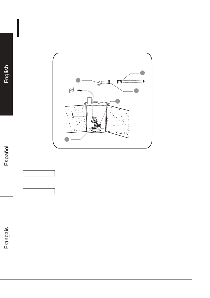
Materials Required for Assembly (not included): Flexible connector, Check valve,
GateValve,PVC pipe, PVC elbow, Thread Tape, PVC Purple Primer, and PVC Cement
Tools Required for Assembly (not included): Wrench, Phillips screwdriver
Risk of suffocation! Keep any packaging materials away
from children – these materials are a potential source of danger,
e.g. suffocation.
DANGER
When using the product, basic safety precautions should always be followed to reduce
the risk of injury including the following:
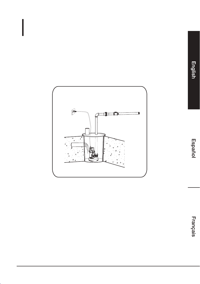
• Connect the pump DIRECTLY to a grounded, GFCI outlet.
Always disconnect the pump from its power source before installing,
inspecting, maintaining, or repairing.
Do not stand in water when the pump is connected.
•
Do not disassemble the motor housing. The motor has NO repairable internal parts,
and disassembling may cause oil leakage or dangerous electrical wiring issues.
•
Do not allow children to operate tool and keep children away from the work area.
•
Always use handle to lift pump. Never use power cord to lift pump. To
avoid skin burns, unplug and allow time for the pump to cool after periods of extended
use.
•
5
WARNING
WARNING

6
Installation
Step 1:
If using a basin, place the pump directly on the bottom of the basin. To prevent
damage set the pump on a solid, level surface. Do not place pump directly on
clay, earth, gravel or sand. A brick or block must be installed under the pump
to provide a solid base.
•
This installation must be in accordance with the National Electric
Code and all applicable local codes and ordinances.
NOTICE
Inlet Pipe
Sump Basin
at least 22” deep
at least 14”diameter

7
Installation
Step 2:
The discharge outlet for this pump has the capability of using either 1-1/2 in.
or 1- 1/4 in. PVC pipe. If 1-1/4" pipe is being used use the provided reducer (4).
Connect a discharge pipe (2) and check valve (1) to the discharge port.
Use thread sealant tape on all connections.
•
•
Do not use flexible hosing in a permanent application.
Install a check valve (required) to prevent back-flow.
NOTICE
NOTICE
2
1
3
4

Installation
8
Step 3:
Placing the pump in a basin and connecting the check valve: connect the discharge
pipe (1) to the elbow (2), union(3),check valve(4), and gate valve(5).
•
Verify the switch has at least 1 in. clearance to the side wall of the basin
and is free to move throughout its movement. If optional control device
or float is used, follow mounting instruction supplied with device or float.
NOTICE
Install a gate valve or ball valve if required by local, regional or state code.NOTICE
3
4
5
2
1

9
Connecting power: Secure power supply cord to discharge pipe using cable or
zip ties to prevent possible switch entanglement. Connect pump power supply
cord to a ground fault circuit interrupter (GFCI) receptacle.
•
Installation
Step 4:
Operating the pump: Fill the basin/pit with water,the pump will start when the
water level has reached the switch-on level. The pump will stop when the water
level has reached the switch-off level.
•
Step 5:

10
SAFETY INFORMATION
CAUTION
This pump is designed for home sump applications. The pump is equipped with a 3-prong
grounding-type power cord. The ball bearings on the motor shafts never need to be lubricated.
This pump has not been tested or approved for use in swimming pools or in salt-water marine
areas. It is also not engineered to be run continuously as a “fountain” or “waterfall” pump.
Because this pump has an oil-filled motor, it should NOT be used in water containing fish.
Pump only water with this pump. For safety, the pump motor has an automatic resetting
thermal protector that automatically will turn off the pump if it becomes too hot. Overuse of
this feature will damage the pump and will void the warranty. Once the thermal protector
detects that the pump has cooled to a safe temperature, it will allow the pump to operate
normally. If the pump is plugged in, it may restart unexpectedly.
•
This pump is made of high-strength, corrosion-resistant materials. It will provide trouble-free
service for a long time when properly installed, maintained, and used. However, inadequate
electrical power to the pump, dirt, or blockage by ice or debris may cause the pump to fail,
eventually bringing about additional water damage. To minimize the potential for water
damage due to pump failure, please carefully read the manual and follow the instructions
regarding common pump problems and remedies.
•
•
Installation
Verify the switch is operating without any obstruction from the pump, piping and basin.15.
Fill the basin/pit with water again. While the pump is draining the basin/pit, verify the
discharge pipe is carrying the water to a point at least 3 ft. away from the foundation.
the pipe must be positioned in a downward slope away from the foundation, so any
remaining water will drain away and not freeze.
•
Step 6:
Secure the basin cover and gasket to the basin to prevent debris from falling into the basin,
prevent personal injury, and to contain gases and/or odors.
•
Step 7:
Ce manuel convient aux modèles suivants
1
Table des matières
Langues :
Manuels Pompe à eau populaires d'autres marques

Sykes AmeriPumps
Sykes AmeriPumps GP100M Guide de dépannage

DUROMAX
DUROMAX XP WX Series Manuel utilisateur

BRINKMANN PUMPS
BRINKMANN PUMPS SBF550 Manuel utilisateur

Franklin Electric
Franklin Electric IPS Manuel utilisateur

Xylem
Xylem e-1532 Series Manuel utilisateur

Milton Roy
Milton Roy PRIMEROYAL Manuel utilisateur


