Alvarado MSG Manuel utilisateur

Alvarado Manufacturing Company, Inc.
12660 Colony Street, Chino, CA 91710
Telephone: +1 (909) 591-8431
Fax: +1 (909) 628-1403
www.alvaradomfg.com
Installation and Maintenance Instructions
Full Height Maximum Security Gate
(MSG / MSG-1 / MSGX / MSGX-PX / MSGX-E / MSGX-S)
PUD1201R5-0

MSG Installation and Maintenance Instructions
Contents
Please read this entire manual before installing or operating the product.
Contents. ......................................................................................................................................................................... 2
Safety Icons..................................................................................................................................................................... 3
Safety Precautions. ......................................................................................................................................................... 3
Common Terms . ............................................................................................................................................................. 4
Congurations Available . ................................................................................................................................................ 5
Tools Required................................................................................................................................................................. 6
Parts List.......................................................................................................................................................................... 6
Installation Overview........................................................................................................................................................ 6
Slab Requirements. .................................................................................................................................................. 6
Drawings and Dimensions............................................................................................................................................... 7
Anchoring Instructions..................................................................................................................................................... 8
Magnetic / Electric Strike Lock Wiring . ......................................................................................................................... 10
Magnetic Lock Specications ................................................................................................................................. 10
Electric Strike Lock Specications . ........................................................................................................................ 10
Power Supply Specications ...................................................................................................................................11
Wiring Instructions . .................................................................................................................................................11
Microswitch Push Bar Wiring Instructions. .................................................................................................................... 13
Card Reader Adapter and Assembly. ............................................................................................................................ 14
Hydraulic Closing Arm Adjustment Instructions............................................................................................................. 15
Maintenance.................................................................................................................................................................. 16
Operational Care..................................................................................................................................................... 16
Gate Finish Care..................................................................................................................................................... 16
Troubleshooting............................................................................................................................................................. 18

MSG Installation and Maintenance Instructions
WARNING Always follow the installation and operating precautions, including the following:
•Read this manual in its entirety before installing or operating the gate. If there are questions, you may contact
Alvarado at (909) - 591 - 8431, Monday through Friday, 7:00AM to 4:00PM PST.
•Use only skilled individuals to install and service the gate.
•The gate is not a toy. Do not allow children to play on or near the gate.
•Follow a proper maintenance schedule using skilled individuals.
•Do not operate the gate if it has been damaged, or is functioning incorrectly, in any manner. Have the
gate repaired by a skilled service person before placing back in use.
•Do not modify or alter the gate.
•Use only Alvarado parts when repairing or maintaining the gate.
•In access control applications, train all personnel that will be using the gate in the proper method of operation.
Ensure that new users are properly trained.
Safety Precautions
The following symbols are used throughout the manual to highlight important information and potential risks when
installing, servicing or using the gate covered in this manual.
WARNING This symbol is used in this manual to warn installers and operators of potential harm. Please
read these instructions very carefully.
This symbol is used in this manual to designate potential conditions that may pose a risk to
pedestrians, personnel, property and equipment. Please read these instructions very carefully.
This symbol is used in this manual to designate useful information for the installer and operator.
Please read these instructions.
Safety Icons
For further assistance, please contact Alvarado's Technical Support Department at
+1(909) 591 - 8431 or visit www.alvaradomfg.com and select the "Support" tab.
Support hours are Monday - Friday 7am - 4pm Pacic Time (excluding USA holidays).
Be prepared to accurately describe the problem and provide the serial number of the gate; this
is printed on a tag attached to the inner frame of the gate.
CAUTION
NOTE
A minimum of two people is required to complete the installation of this product.
SAVE THESE INSTRUCTIONS
Upon completion of the installation process, it is the installer's
responsibility to provide the project or site manager with this
Installation and Maintenance Instruction manual.
PUD1201R5-0

MSG Installation and Maintenance Instructions
Common Terms
• Fail Safe - Gate unlocks in the event of power loss. The gate will relock when power is reapplied. All magnetic locks
are Fail Safe. Fail Safe electric strike locks are available as an option.
•Fail Lock - Gate remains locked when power is removed (or lost). The gate will unlock only when both power and
an activation contact are supplied. All electric strike locks are Fail Lock unless otherwise specied.
Magnetic Locks are not available in Fail Lock mode.
• Activation - Alvarado's gates require the use of a timed contact switch to lock and unlock. The gate will not
re-engage until the switch is released and the gate is closed.
•Mesh Inll - The mesh inll is a diamond pattern steel mesh that is attached to the interior portion of the gate. The
purpose is to prevent persons from reaching through the gate. This component is available for all
models.
•Microswitch Push Bar - This is an electrically operated mechanical push bar . If there is power loss, the bar will
default to the condition specied for the lock in use. This component is not available for the
MSG or MSG-1 models.
•Mechanical Push Bar - Mounted on the exit side, when the bar is pushed in the exit direction, the latching bolt is
mechanically retracted allowing the user to exit. This allows emergency exiting at any time
through the gate regardless of power conditions. This option is available only on: MSG-1,
MSGX-E, and MSGX-S models.
• Dead Bolt Lock - A keyed lockset that is used to lock the gate in a closed position. A key is required to unlock the
gate on either the entry or exit side of the gate.
•Magnetic Lock - Magnetic lock oers up to 1200 pounds of holding force. Power (low-voltage 12VDC) is supplied
to the lock to energize the magnetic lock. When the gate is closed, the latch plate (mounted to
the gate) is held against the magnetic lock (mounted on the gate frame) when power is applied.
The gate is unlocked by removing power from the magnetic lock and the patron pulls the gate
open in the entry direction or pushes the gate open in the exit direction. This is standard only on
the MSGX and MSGX-PX models.
•Electric Strike Lock - A lock where power (low-voltage 12VDC) is supplied to the lock to release the mechanism to
allow the gate to open. Power is then removed to allow the strike to be in the lock position.
This lock is standard on the MSGX-E and MSGX-S models.
• Universal Card Reader Mounting Plate - A mounting plate is attached to the latch post of the gate on the entry,
exit, or both sides.The mounting plate is a universal style plate that an
additional device specic plate may be added in order to t the reader that
is required. This option is available on: MSGX, MSGX-PX, MSGX-E, and
MSGX-S models.
•Push-To-Exit Remote Button Switch - A 3.15in square switch box assembly constructed of stainless steel with a
DPDT (double pole double throw) push button switch. The switch is eld
wired into the strike or magnetic lock power cable to unlock the gate from
a remote position such as a guard shack. This optional component
is available for: MSGX, MSGX-PX, MSGX-E, and MSGX-S models.
• Magnetic Sensor Switch - A two piece switch magnet mounted on the gate and the latch post. It is used to monitor
whether the gate is open or closed. The switch is a SPST (single pole single throw)
contact supplied with two lead in wires for eld connection. This option is available for all
MSG models.
PUD1201R5-0

MSG Installation and Maintenance Instructions
Alvarado gates in this manual come in the following congurations. Please read each model description carefully to
ensure you understand the functionality of the gate you are installing.
Model Entry Hardware Exit Hardware Operation
MSG Pull handle No hardware Gate swings in one direction
MSG-1 Key lock control with pull handle Mechanical push bar
Gate swings in one direction.
Gate includes stop gap.
Inll mesh to prevent activation through push bar.
MSGX Magnetic lock (Fail Safe) with pull handle No hardware Gate swings in one direction.
MSGX-PX Magnetic lock (Fail Safe) with pull handle Microswitch push bar Gate swings in one direction.
Inll mesh to prevent activation though push bar.
MSGX-E Electrc strike (Fail Lock), key lock control with
pull handle Mechanical push bar
Gate swings in one direction.
Gate includes stop gap.
Inll mesh to prevent activation through push bar.
MSGX-S Electric strike lock (Fail Lock) and pull handle No hardware Gate swings in one direction.
Gate includes stop gap.
Congurations Available (Cont.)
Congurations Available
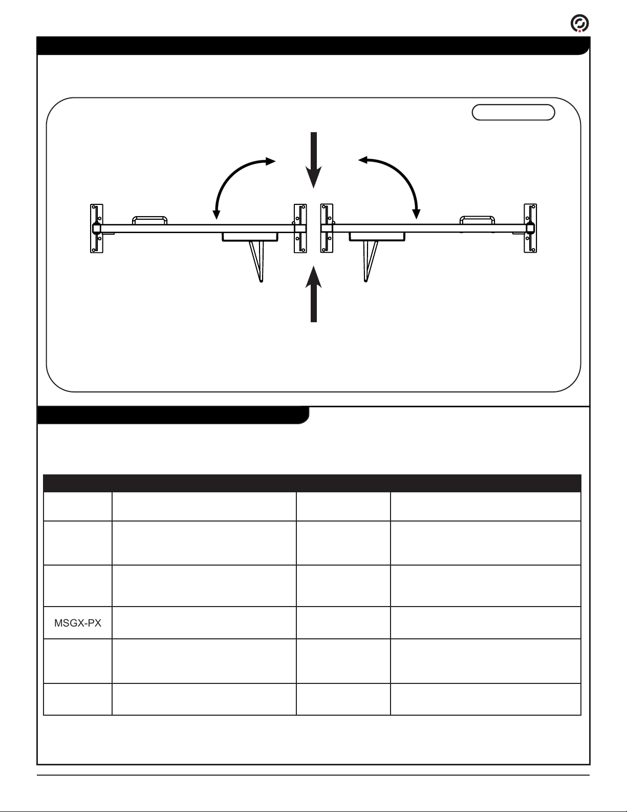
The Maximum Security Gate models are available in a left-hand or right-hand swing directions. See below to
determine the entry and exit direction for both swing directions.
Figure 1
Left-HandRight-Hand
Entry Direction
Exit Direction
PUD1201R5-0

MSG Installation and Maintenance Instructions
Parts List
Tools Required
Installation Overview
Slab Requirements
•Heavy Duty Drill or Rotary Hammer
•5/8" Concrete Drill Bit
•Torque Wrench (ft-lbs)
•Shop Vac
•Tape Measure
•Chalk Line
•Safety Glasses
The overall steps to correctly install the Maximum Security Pedestrian Gate are below:
1) Determine gate location; taking into account power and activation wiring stub requirements (if applicable).
2) Anchor the gate and attach the closing arm hinge.
3) Connect activation wiring (if applicable).
4) Connect low-voltage power (if applicable).
The must be installed on a level concrete pad with a minimum thickness of 4 inches.
WARNING DO NOT INSTALL ON ASPHALT.
•Gate in frame
•This installation guide
•Power supply (for select models)
•Anchor package:
•3/8" anchors (2" length - Qty 8)
•3/8-16 x 2 1/2" HHSC (Qty 8)
•3/8" Flat washers (Qty 8)
•Push bar or handle (optional)
PUD1201R5-0

MSG Installation and Maintenance Instructions
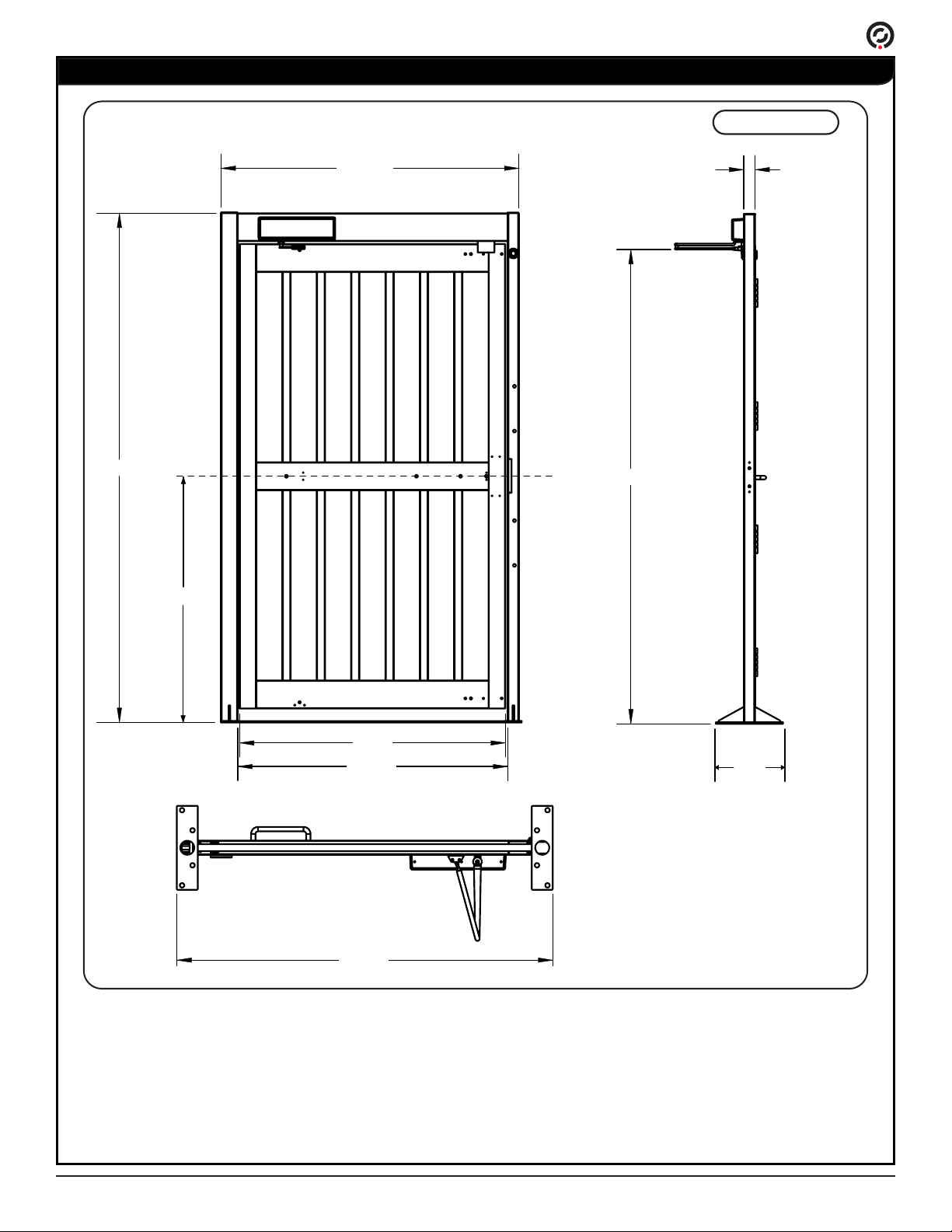
Drawings and Dimensions
91.00
53.25”
44.00
84.50
2.00
12.00
47.5”
48.25”
53.75”
Figure 2
PUD1201R5-0

MSG Installation and Maintenance Instructions
Anchoring Instructions
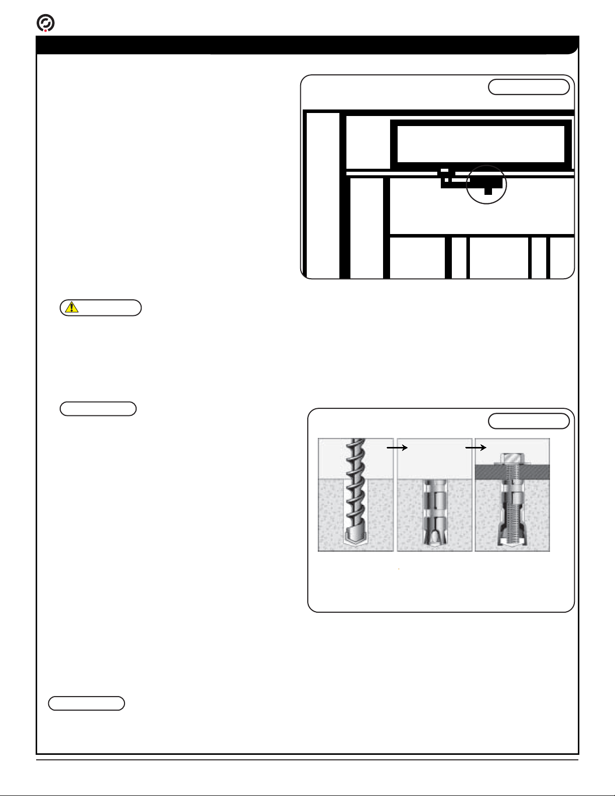
1) The hydraulic arm is detached from the gate for
ease of shipping. Before removing the gate the from
the shipping crate, reattach the hydraulic arm hinge
to the gate using (2) 1/4" machine screws. [Figure 3].
2) Determine the installation location of the gate, taking
into consideration the minimum width opening
required; refer to Drawings & Dimensions section
on Pg. 7 for minimum installation requirements.
Once the installation location is conrmed, snap a
chalk line on the oor to mark the centerline of the
gate. The chalked centerline should be at least 6"
longer than the overall width of the gate.
3) Set the gate on the chalk line, facing in the correct
direction of operation.
4) Mark the center locations of the (4) four anchor holes
in each of the frame's base plates.
5) Move the gate to the side and drill a 5/8" diameter
hole to a depth of 3" at the center of each marked
location. For terrazo, ceramic tile, or brick veneer
installations, add the thickness of the nished oor
material to anchor the hole depth.
6) Vacuum out the holes thoroughly. If the holes are not
clean, the anchors will not tighten.
7) Insert one anchor into each drilled hole. Ensure
the anchors are ush with the concrete oor or
nished surface and the threads are down as shown
in [Figure 4].
NOTE
It is recommended to brace the top of the gate with supplemental products or with exisiting structure to increase
rigidity and support.
CAUTION
Care must be exercised when moving the gate
The gate weighs approximately 400lbs. Until
the gate is securely fastened to the concrete
foundation, secure the gate / frame assembly
to prevent the unit from falling.
NOTE
The gate should swing in the exit direction.
Refer to Congurations Available on Pg. 5 if
there is any uncertainty of orientation.
Figure 3
Figure 4
Drill hole.
Clean hole.
Vacuum debris.
Insert the anchors
with the thread side
down. The anchors
must be a with the
surface.
Insert the washer.
Insert the bolt.
Tighten bolt.
PUD1201R5-0

MSG Installation and Maintenance Instructions
Anchoring Instructions (Cont.)
8) Return the gate back over the anchor holes. Anchor
both sides with four (4) each 3/8-16 x 2 1/2" HHCS
bolts and at washers. Make sure the bolts are snug
to keep gate secure.
9) Verify the gate is level in all directions. Adjust and shim as
necessary.
10) Torque all anchor bolts (8 total) to 25 ft-lbs. Verify that the gate is
level.
This completes the physical installation of the Maximum Security Gate.
Proceed to next section for wiring diagrams for electrically controlled models.
PUD1201R5-0

MSG Installation and Maintenance Instructions
Magnetic / Electric Strike Lock Wiring
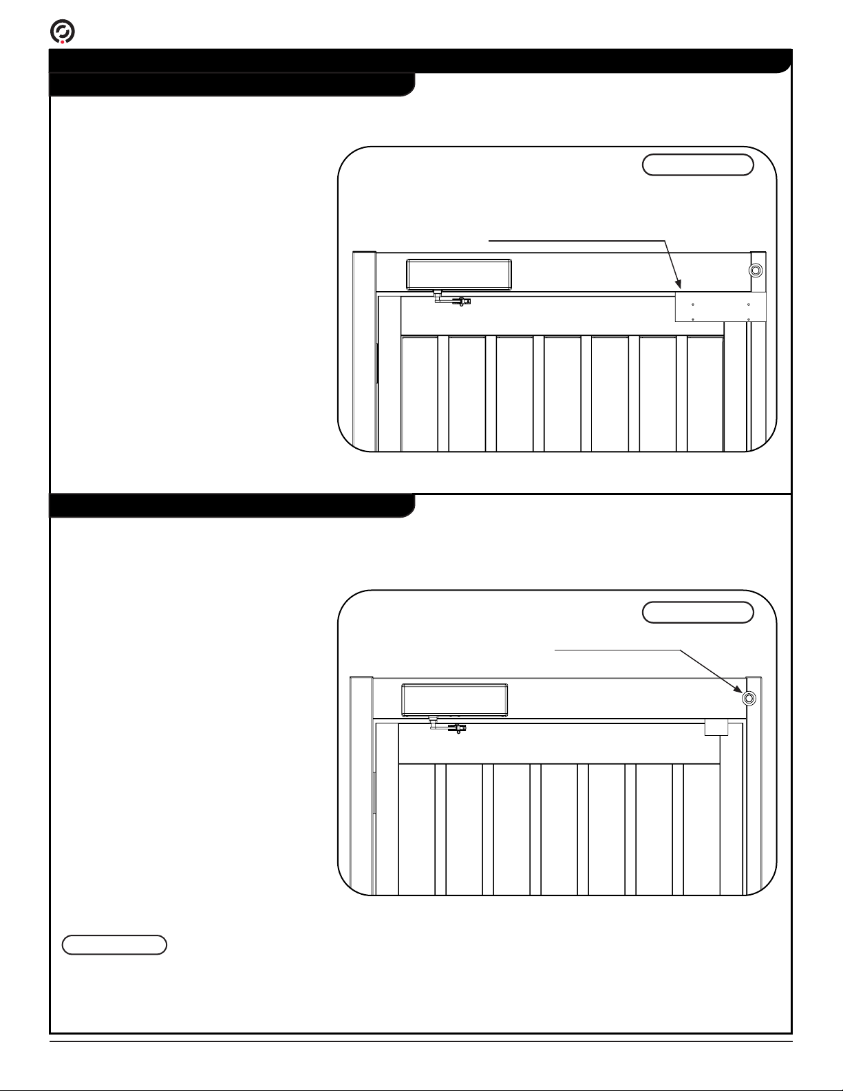
If a magnetic lock is used, the lock and wires are located on the gate frame towards the top of the gate door.
[Figure 5]
If an electric strike lock is used, (2) two white wires attached to the lock will be coming out of the wire access hole.
Either side of the access hole can be plugged if necessary. A 1/2" pipe thread hole plug is supplied. [Figure 6]
Magnetic Lock Specications
Electric Strike Lock Specications
Magetic Lock (Standard):
Voltage: +12VDC
Current: 0.25A
Switch Contact: Normally Closed
Holding Force: 1200lbs.
Wire Lead:
•Red - +12VDC Input
•Black - Ground
Electric Strike Lock (Standard):
Voltage: +12VDC
Current: 0.25A
Switch Contact: Normally Open
Normally Closed
Wire Lead:
•Red - +12VDC Input
•Black - Ground
NOTE
• Normally Open refers to Fail Lock & Normally Closed refers to Fail Safe.
• Cable runs are not to exceed 50 feet.
Figure 5
Figure 6
Wire access hole
Magnetic lock and wires
PUD1201R5-0
Ce manuel convient aux modèles suivants
5
Table des matières
Autres manuels Alvarado Clôtures et portails