Altair FA-524 Manuel utilisateur

FA-524/FA-724
OWNERS MANUAL
ACTIVE CROSSOVERS
EQUIPOS EUROPEOS ELECTRÓNICOS, S.A.L.
AVDA. DE LA INDUSTRIA, 50. 28760 TRES CANTOS (MADRID)
www.altairaudio.com
ALTAiR

CONTENTS
1. SWITCHES, CONTROLS, ADJUSTMENTS AND CONNECTORS 4
FRONT PANEL 4
REARPANEL 5
2. WORKING PRECAUTIONS 6
3. INSTALLATION 6
CHANGINGTHEVOLTAGE 6
CHANGING THE FUSE 6
CONNECTION TO THE MAINS 7
INPUT CONNECTION 7
OUTPUT CONNECTION 8
GROUND LINK 9
4. OPERATION 10
MODES OF OPERATION 10
LEVELCONTROL 11
SIGNAL, THRESHOLD AND OVERLOAD INDICATOR 11
MUTE 12
PHASE SWITCH 12
PHASE ADJUSTMENT BETWEEN WAYS 12
5. OPTIONS 13
FREQUENCY CARD (TC-66) 13
EQUALIZER CARD (TE-67) 13
DELAY CARD (TD-69) 13
SECURITY COVER (TP-1) 14
LOCKABLE SECURITY COVER (TS-1) 14
6. SPECIAL OPERATIONS 14
FREQUENCY CARDS 15
FREQUENCYCARDCONFIGURATION 15
OVERLAPPEDFREQUENCYCARDCONFIGURATION 19
PLACING A FREQUENCY CARD 19
MODES OF OPERATION CONFIGURATION 20
THREE STEREO WAYS (ONLY FA-724) 20
TWO STEREO WAYS 20
SIX MONO WAYS (ONLY FA-724) 21
FIVE MONO WAYS (ONLY FA-724) 21
FOUR MONO WAYS 21
THREE MONO WAYS 22
LIMITER ADJUSTMENT 22
EQUALIZERCARD 23
EQUALIZER CARD CONFIGURATION 24
GAINCALCULATION 24
FILTER FREQUENCY CALCULATION 25
BANDWIDTH CALCULATION (Q) 26
BAND GAIN VARIATION 27
NONSTANDARDEXAMPLESCONFIGURATION 28
2

3
PLACING AN EQUALIZER CARD 29
DELAYCARD 30
DELAY CARD CONFIGURATION 30
PLACING A DELAY CARD 31
7. BLOCK DIAGRAM AND OPERATION EXPLAIN 32
8. REPAIR GUIDE 35
9. TECHNICAL SPECIFICATIONS 37
10. GRAPHS 38
11. WARRANTY 39

1. SWITCHES, CONTROLS, ADJUSTMENTS AND CONNECTORS
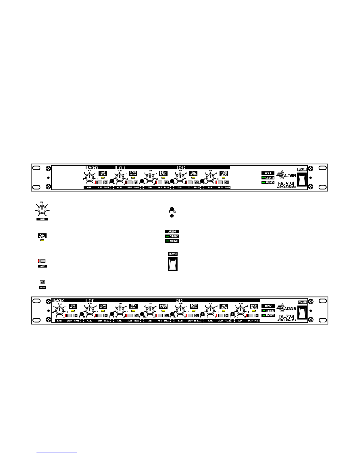
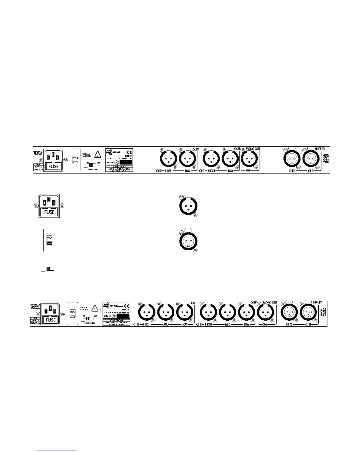
These are the switches, controls, adjustments and connectors that you could find in your crossover ALTAIR. The description and explana-
tion of each one of them, you will find in the corresponding section.
FRONT PANEL
LEVEL CONTROL. PHASEADJUSTMENTBETWEENWAYS.
SIGNAL, THRESHOLD AND OVERLOAD INDICATOR. TURNONANDOPERATIONMODE(STEREO/MONO)INDICATOR.
MUTE (WITH INDICATOR LED). POWER SWITCH.
PHASESWITCH.

REARPANEL
MAINSCONNECTORANDFUSEHOLDER. OUTPUTCONNECTOR.
VOLTAGESELECTOR. INPUTCONNECTOR.
EARTH LINK SWITCH.

2. WORKING PRECAUTIONS
The manufacturer is not made responsible of any damage occurred in the
crossover unit outside the limits of the warranty or that had been produced by not
keeping in mind the working precautions.
First at all, make sure that the mains voltage to which the crossover is to be
connected is the same that the voltage selector setup placed at the crossover rear
panel
DANGER: In the crossover unit there is high voltages, doesn't open it. The
crossover unit doesn't contain elements which could be repaired by the user.
Whenever crossover unit is connected to the mains, contains elements with high
tensions. In order to disconnect the crossover unit completely, you must disconnect
it of the mains.
Protect the crossover unit of the rain and humidity. Make sure of that no liquid
or object introduces in their interior. If a liquid is poured over the crossover unit,
disconnect it of the mains and consult a qualified technical service.
Don't place the crossover unit near heat sources.
3. INSTALLATION
CHANGINGTHEVOLTAGE
The crossover unit is set to operate at 230V, 50-60Hz and at 115V, 50-60Hz.
Make sure that the crossover unit is disconnected of the mains.
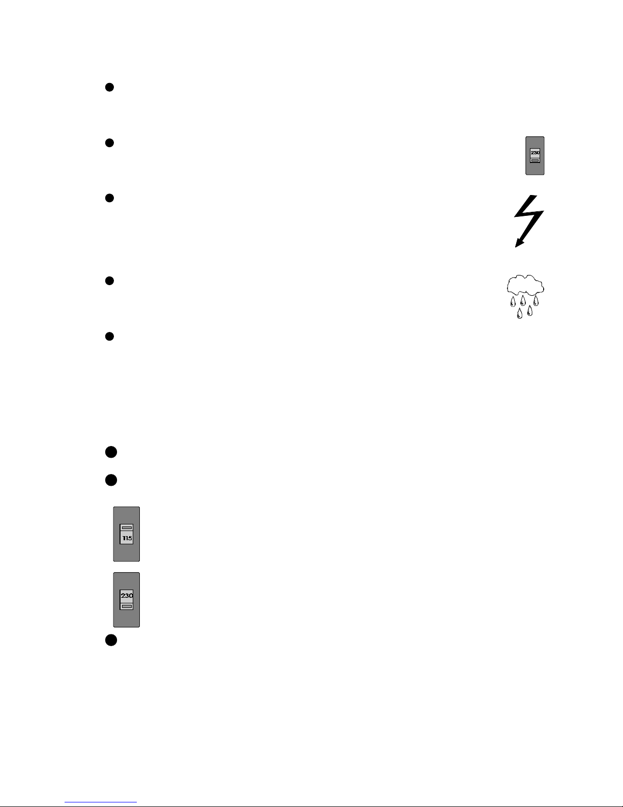
Set up the voltage selector, placed at the crossover rear panel, in the position
that shows the voltage which you want to connect it.
Crossover set up 115 V.
Crossover set up 230 V.
Make sure that the fuse is the right one for the selected voltage:
T1A ---------> 115V.
T0,5A ----------> 230V.
CHANGING THE FUSE
The crossover unit is factory set up with a T0,5A FUSE, adequate in order to
work with a mains of 220-240V, 50-60Hz.
1
2
3
6

7
Make sure that the crossover unit is disconnected of the mains.
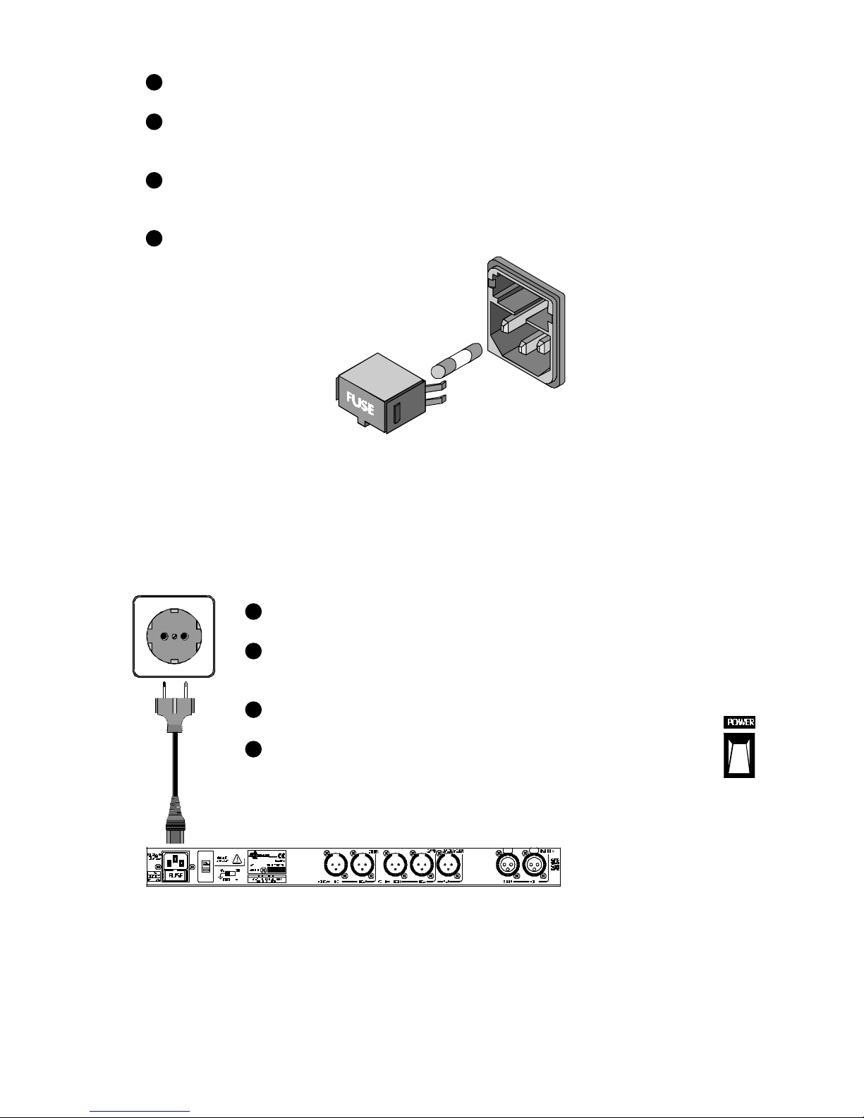
In the crossover rear panel, is placed the mains connector and the fuse holder. The box
bellow this mains connector is called fuse holder. Take out the fuse holder.
Upon extracting the fuse holder, the fuse will appear, take out it and change for the new
one.
Insert the fuse holder into the mains connector again.
CAUTION: Always make sure upon changing the fuse, of that is the adequate for the se-
lected mains voltage (T1A for 115V and T0,5A for 230V).
CONNECTION TO THE MAINS
The connection of the crossover power supply to the mains takes place by a tripolar
cord provide by the factory.
Make sure that the crossover power switch, is at position 0 (turned off).
Insert the female connector of the tripolar cable into the crossover power
supply male connector, placed at the rear panel.
Insert the male connector of the tripolar cable into the mains plug.
Turn on the crossover power switch. In that moment the MODE LED
indicator will light, indicating that the crossover is turned on.
CAUTION: Make sure that the mains tension to the one which is going to
connect the crossover unit is correct, as well as their fuse is the adequate.
INPUT CONNECTION
The crossover signal input, is carried out through two XLR-3-31 females connectors, one
per channel. The input connections are balanced, with a nominal impedance of 20 KΩ(10
KΩunbalanced).
2
1
4
3
1
4
3
2

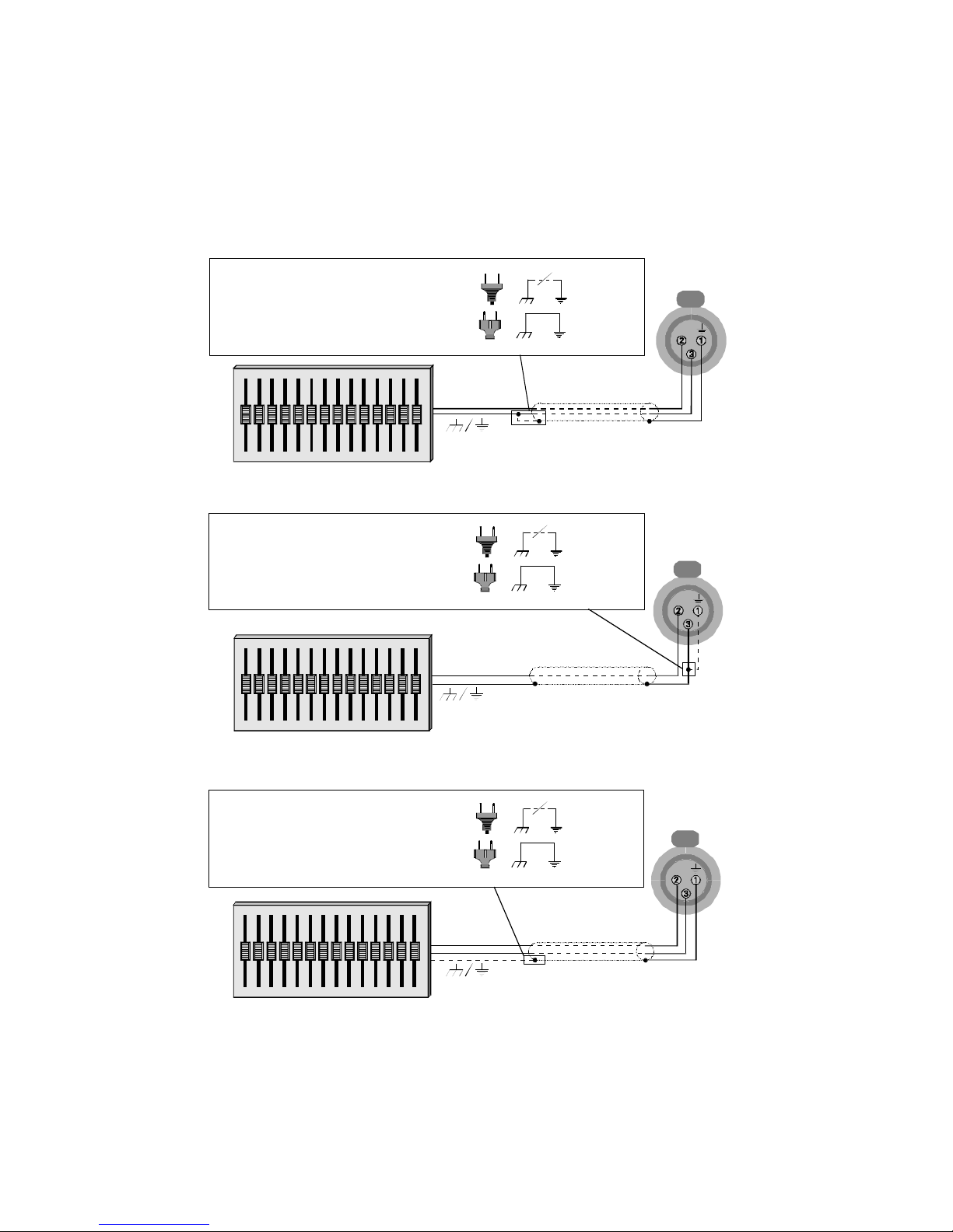
The following pictures shows some of the different possibilities of connection, relying on
the type of input signal, balanced or unbalanced and according to the ground configuration
of the equipment (floating or ground-referenced).
UNBALANCED INPUT: This type of connection will be used when the sound source doesn't
provide of balanced output. If it is possible, will be employed the connection type 1.
1) Using twin-lead shielded cable:
2) Using single conductor coax cable:
BALANCED INPUT:
OUTPUT CONNECTION
The crossover output signal is carried out through XLR-3-32 males connectors, one per
way (7 for the model FA-724 and 5 for the model FA-524). The outputs are balanced, with a
nominal impedance of 100Ω.
CROSSOVER
UNIT
+
-
+
SOUND
SOURCE
+
+-CROSSOVER
UNIT
Floating sound source ( / ) : Close.
Ground-referenced sound source ( / ) : Open.
Floating sound source ( / ) : Close.
Ground-referenced sound source ( / ) : Open.
SOUND
SOURCE
+
-
CROSSOVER
UNIT
SOUND
SOURCE
-
+
Floating sound source ( / ) : Close.
Ground-referenced sound source ( / ) : Open.
8

9
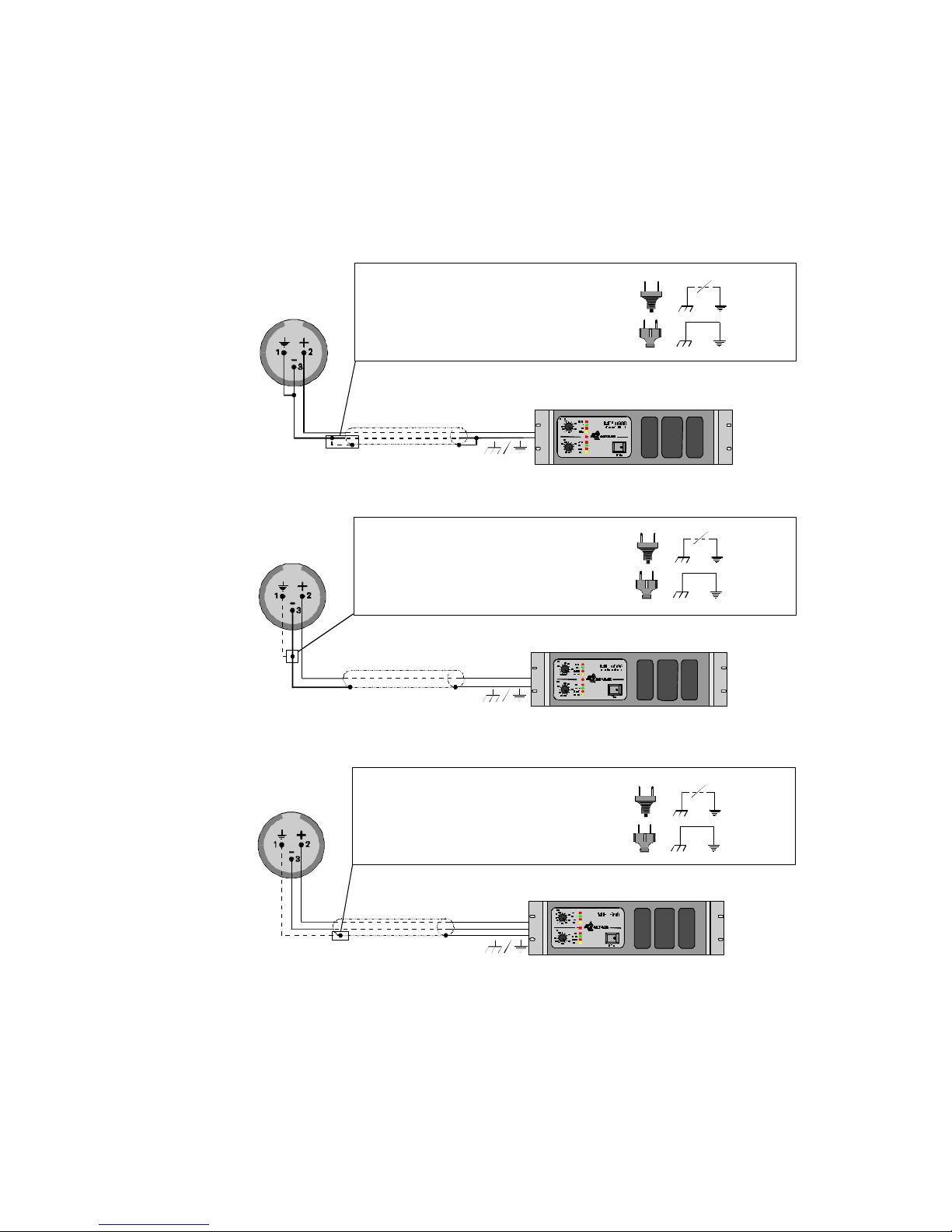
The following graphics shows some of the different possibilities of connection, relying
on the type of the power amplifier input signal, balanced or unbalanced and according to
the ground configuration of the equipment (floating or ground-referenced).
UNBALANCED OUTPUT: This type of connection will be used when the power amplifier
doesn't provide of balanced input. If it is possible, will be used the connection type 1.
1) Using twin-lead shielded cable:
2) Using single conductor coax cable:
BALANCED OUTPUT:
GROUND LINK
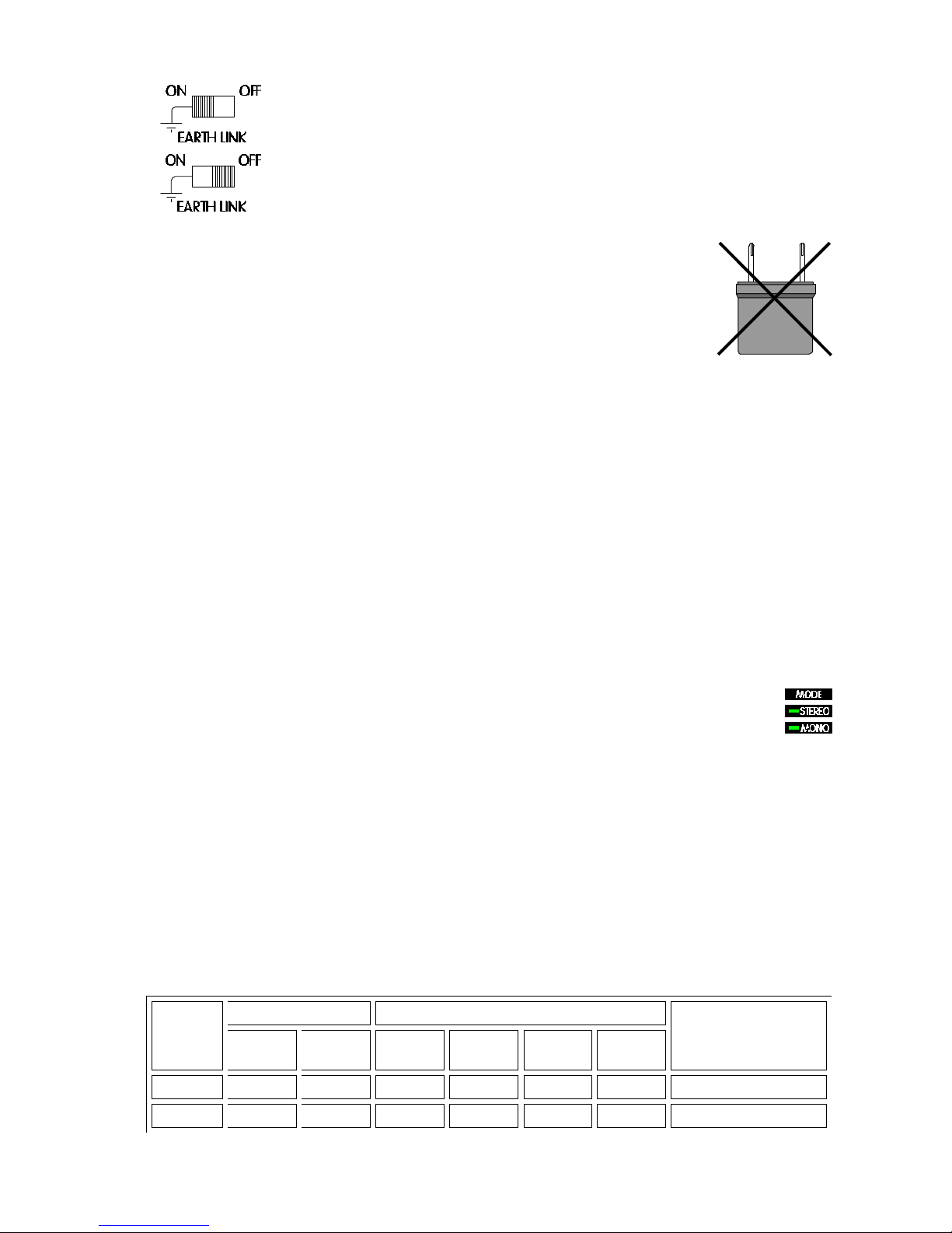
In some installations, it might be necessary to isolate the crossover electric ground, from
the system mains earth, in order to avoid ground loops, that could generate unwanted
noises, for this reason, the crossover provides an EARTH-LINK switch placed at the rear panel
in order to lift the mains earth from the crossover electric ground.
CROSSOVER
UNIT
POWER
AMPLIFIER
CROSSOVER
UNIT
POWER
AMPLIFIER
+
Floating power amplifier ( / ) : Close.
Ground-referenced power amplifier ( / ) : Open.
+
Floating power amplifier ( / ) : Close.
Ground-referenced power amplifier ( / ) : Open.
CROSSOVER
UNIT
POWER
AMPLIFIER
Floating power amplifier ( / ) : Close.
Ground-referenced power amplifier ( / ) : Open.
+
-

MAINS EARTH LINKED WITH THE CROSSOVER ELECTRIC GROUND
MAINS EARTH LIFTED FROM THE CROSSOVER ELECTRIC GROUND
CAUTION: Sometimes, lifts the mains earth, using a ground-lift connector,
the one which undoes the ground loop also, but this is very dangerous,
since if for any circumstance part of the mains signal is derived to the
chassis, could cause a short-circuit through our body, upon having elimi-
nated one of the working precautions of the unit. For this circumstance,
NEVER lift the mains earth (lift the crossover EARTH-LINK switch) in order to
avoid possible accidents.
4. OPERATION
The crossover utility, is divide the audible band (20Hz to 20KHz) in smaller bands,
whose sum restores the audible band again. Once separate and tried meetly, the different
bands are amplified and reproduce for separating giving a multiamp system like result. This
division is carried out so that the different cabinet ways only receives the part of the band that
they are capable of reproducing, avoiding possible breaks, and an unnecessary warming up,
and so that the power amplifiers only amplify the signal that is going to reproduce the cabinet
way that are feeding, avoiding that unnecessarily warms, amplifying signals that are not been
going to reproduce.
MODES OF OPERATION
The crossover can be configured as either a stereo mode or mono mode. The
crossover configuration is shown in the front panel of the unit by the MODE LED
indicator (STEREO / MONO).
In STEREO mode operation, will provide of two totally independent crossover channel
inputs, with 2 or 3 ways for the FA-724 and 2 ways for the FA-524.
In MONO mode operation, will only have one input channel: CH1 (the channel CH2 will
be disabled, for the one which any signal that inserts in it, will be lost, since it won't appear in
the output), and of 4, 5 or 6 ways for the FA-724 and 3 or 4 ways for the FA-524.
Besides these mentioned ways, exists an additional subwoofer mono way (SW), whose
signal will be the sum of the input channels CH1 and CH2 in stereo mode, and the input
channel CH1 in mono mode. It is important emphasize that in stereo mode, this output upon
adding the signals of the input channels CH1 and CH2, if only inserts signal for one of the
input channels, will only have the half of the signal in the output.
The following table list the possible configuration of the crossovers FA-724 and FA-524:
MODEL STEREOMODEMONOMODESUBWOOFER
OUTPUT
THREE
WAYS TWO
WAYS SIX
WAYS FIVE
WAYS FOUR
WAYS THREE
WAYS
FA-524 YES YES YES YES YES YES YES
FA-724 NO YES NO NO YES YES YES
10
Ce manuel convient aux modèles suivants
1
Table des matières