Alstom SF6 Manuel utilisateur
Contents
Instruction manual
D1530EN/04
1/6
08--2012
©ALSTOM 2010. All rights reserved. Information contained in this document is indicative only. No representation or warranty is given or should be relied
on that it is complete or correct or will apply to any particular project. This will depend on the technical and commercial circumstances. It is provided
without liability and is subject to change without notice. Reproduction, use or disclosure to third parties, without express written authority, is strictly
prohibited. GRID
SF6circuit breaker
GL314 P.
With spring operating system
FK3--07
This equipment contains a greenhouse effect gas (SF6), covered by the Kyoto Protocol, with a
Global Warming Power of 22200 (GWP).
The SF6must be recovered and must not be released into the atmosphere.
For more information on use and handlling of SF6refer to norm CEI 62271 : High-voltage switchgear
- Part 303 : Use and handling of Sulphur Hexafluoride (SF6).
Administrator Emission Prepared by Approved by
AHT 22--03--2010 J. Bossu G. Doummar

Contents
Instruction manual
D1530EN/04
2/6
08--2012
©ALSTOM 2010. All rights reserved. Information contained in this document is indicative only. No representation or warranty is given or should be relied
on that it is complete or correct or will apply to any particular project. This will depend on the technical and commercial circumstances. It is provided
without liability and is subject to change without notice. Reproduction, use or disclosure to third parties, without express written authority, is strictly
prohibited. GRID
This page is intentionally blank.

Contents
Instruction manual
D1530EN/04
3/6
08--2012
©ALSTOM 2010. All rights reserved. Information contained in this document is indicative only. No representation or warranty is given or should be relied
on that it is complete or correct or will apply to any particular project. This will depend on the technical and commercial circumstances. It is provided
without liability and is subject to change without notice. Reproduction, use or disclosure to third parties, without express written authority, is strictly
prohibited. GRID
Safety
Product safety sheets Appendices
Technical data
Technical characteristics Rating plate
Description and Functionalities
General Description of the Switchgear P12--0001EN/02
Description of the breaking chamber P12--1001EN/02
Pole operation (principle of breaking) P13--0001EN/02
Monitoring SF6gas P20--0001EN/02
Packaging -- Transport and Storage
Packing -- Marking -- Storage P22--0001EN/02

Contents
Instruction manual
D1530EN/04
4/6
08--2012
©ALSTOM 2010. All rights reserved. Information contained in this document is indicative only. No representation or warranty is given or should be relied
on that it is complete or correct or will apply to any particular project. This will depend on the technical and commercial circumstances. It is provided
without liability and is subject to change without notice. Reproduction, use or disclosure to third parties, without express written authority, is strictly
prohibited. GRID
Installation
General mounting recommendations P30--0001EN/02
Tightening torque values P31--0001EN/02
General fitting recommendations P31--0002EN/02
Verification of the presence of SF6gas in the
poles
P31--0501EN/03
Mounting the frame P31--1001EN/03
Hoisting and installing the pole P31--2001EN/03
Mounting the power supply terminals with prepar-
ation of the contact surfaces
P31--5001EN/02
Mounting the operating mechanism P31--7901EN/02
Calculating the SF6gas filling pressure for use of
the pressure gauge (tools)
P31--9001EN/02
Filling with SF6gas P32--0001EN/03
Commissioning
Inspection prior to commissioning P34--0001EN/03
Test report prior to commissioning RES 310 M EN/10
Acceptance criteria CAEN 104 100/3/004

Contents
Instruction manual
D1530EN/04
5/6
08--2012
©ALSTOM 2010. All rights reserved. Information contained in this document is indicative only. No representation or warranty is given or should be relied
on that it is complete or correct or will apply to any particular project. This will depend on the technical and commercial circumstances. It is provided
without liability and is subject to change without notice. Reproduction, use or disclosure to third parties, without express written authority, is strictly
prohibited. GRID
Maintenance
Maintenance plan P51--0001EN/02
Limit of electrical wear P51--0501EN/02
Control of contact densimeter thresholds P51--1001EN/03
Intervention on the operating mechanism P51--3001EN/03
Replacing the FK3--07 operating mechanism P51--8001EN/02
Appendices
Tools and accessories P60--0001EN/03
Product safety sheets PS0000/EN
Manual operations (FK3--07) 48.020.249EN
End of equipment service life
Dismantling and recovery of
circuit breaker components
P80--0001EN/02
Managing SF6gas P80--0002EN/02
Directives for handling used SF6 gas
and its by--products
P81--0001EN/02

Contents
Instruction manual
D1530EN/04
6/6
08--2012
©ALSTOM 2010. All rights reserved. Information contained in this document is indicative only. No representation or warranty is given or should be relied
on that it is complete or correct or will apply to any particular project. This will depend on the technical and commercial circumstances. It is provided
without liability and is subject to change without notice. Reproduction, use or disclosure to third parties, without express written authority, is strictly
prohibited. GRID
This page is intentionally blank.
Description and Functionalities
General Description of the Switchgear
P12--0001EN/02
1/6
01--2011
© ALSTOM 2010. All rights reserved. Information contained in this document is indicative only. No representation or warranty is given or should be relied on
that it is complete or correct or will apply to any particular project. This will depend on the technical and commercial circumstances. It is provided without
liability and is subject to change without notice. Reproduction, use or disclosure to third parties, without express written authority, is strictly prohibited.
GRID
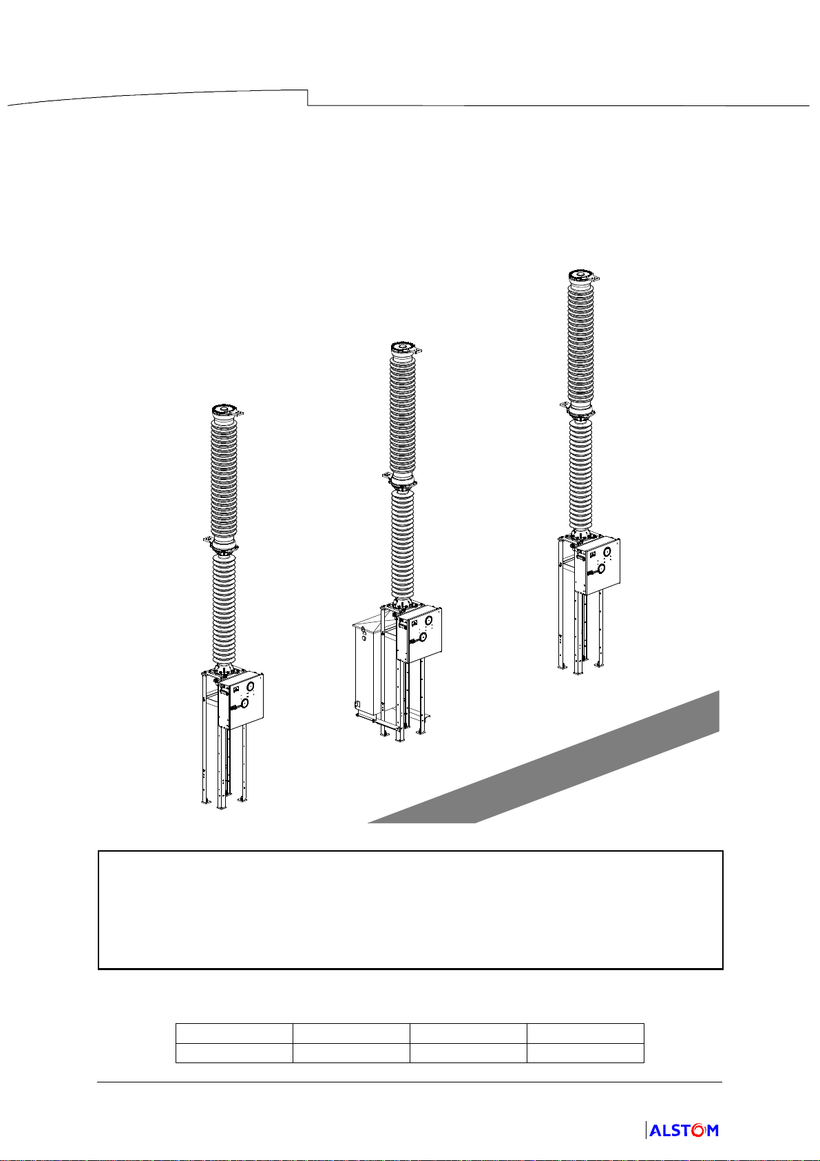
GL314 P circuit breaker
with FK3--07 spring operating system
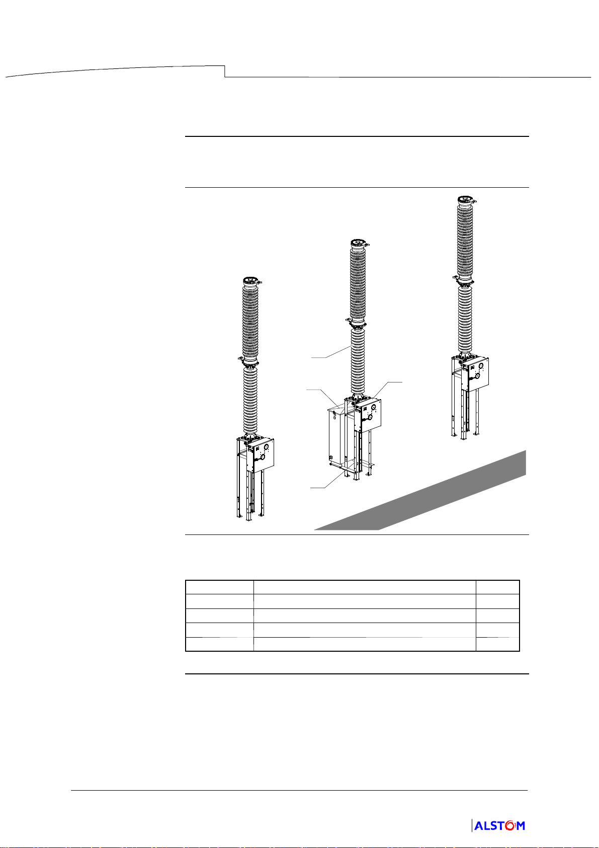
Description The device comprises three poles actuated, respectively, by three spring
operating mechanisms.
Illustration
DC
A
B
Table of Elements The following table lists the main components of the circuit breaker :
Mark Component Page
ACircuit breaker pole 2
BSupport frame 3
COperating mechanism 4
DCable box 5
Description and Functionalities
General Description of the Switchgear
P12--0001EN/02
2/6
01--2011
© ALSTOM 2010. All rights reserved. Information contained in this document is indicative only. No representation or warranty is given or should be relied on
that it is complete or correct or will apply to any particular project. This will depend on the technical and commercial circumstances. It is provided without
liability and is subject to change without notice. Reproduction, use or disclosure to third parties, without express written authority, is strictly prohibited.
GRID
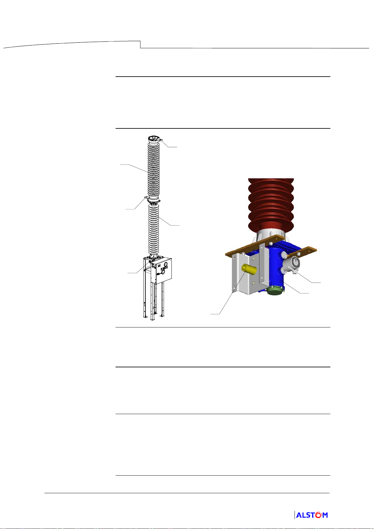
Circuit breaker pole
Description The circuit breaker pole is made up of three main components :
DThe breaking chamber (1).
DThe support column (2).
DThe mechanism casing (3).
Illustration
2
1
5
5
3
7
4
3
Breaking
chamber
The pole comprises a breaking chamber (1), in ceramic casing, placed
vertically, with the upper end of each fitted with a power supply terminal
(5).
Support Column Comprising one or more ceramic insulators,the support column (2) is
used to provide earthing insulation for the circuit breaker and encloses the
insulating operating rod, attached to the moving parts of the breaking
chamber.
Mechanism casing A casing (3), located at the base of the column, encloses the operating
rod--crank attached to the moving parts.
The filling and monitoring device for the SF6(7) gas is also located in the
casing.
An external sleeve (4) mechanically connects the pole to the operating
mechanism.
Description and Functionalities
General Description of the Switchgear
P12--0001EN/02
3/6
01--2011
© ALSTOM 2010. All rights reserved. Information contained in this document is indicative only. No representation or warranty is given or should be relied on
that it is complete or correct or will apply to any particular project. This will depend on the technical and commercial circumstances. It is provided without
liability and is subject to change without notice. Reproduction, use or disclosure to third parties, without express written authority, is strictly prohibited.
GRID
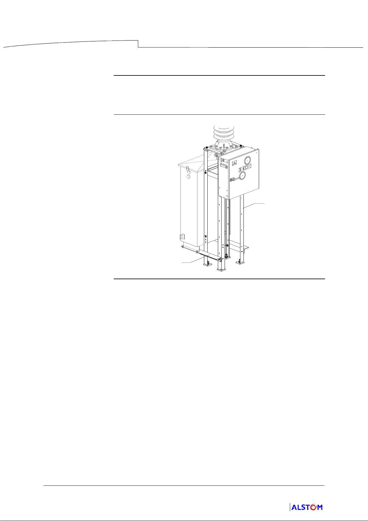
Support frame
Description The support frame (9) is attached to the ground and supports all of the
circuit breaker components.
The support frame can by provided by the client or by ALSTOM Grid.
The support frame (9) is equipped with a cabinet (10).
Illustration
10
9
Description and Functionalities
General Description of the Switchgear
P12--0001EN/02
4/6
01--2011
© ALSTOM 2010. All rights reserved. Information contained in this document is indicative only. No representation or warranty is given or should be relied on
that it is complete or correct or will apply to any particular project. This will depend on the technical and commercial circumstances. It is provided without
liability and is subject to change without notice. Reproduction, use or disclosure to third parties, without express written authority, is strictly prohibited.
GRID
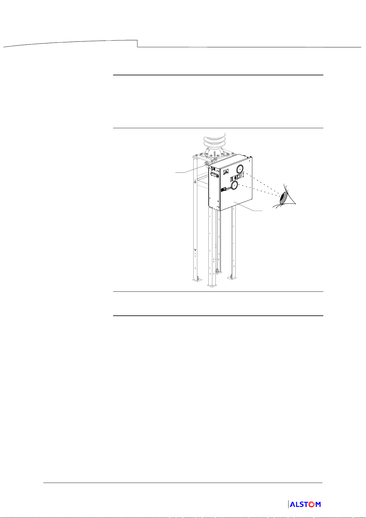
Operating mechanism
Description The operating mechanism (11) is an FK3--07 type spring operating
mechanism.
The door of the operating mechanism is fitted with two inspection windows.
These windows are used to view the optical position indicators for the
circuit breaker and the status of the closing spring.
Illustration
3
11
Fixings The operating mechanism is fixed to the casing (3).
Ce manuel convient aux modèles suivants
2
Table des matières
Autres manuels Alstom Disjoncteur


