AlphaGen ACX2000i Manuel utilisateur

AlphaGen ACX2000i 120V Portable Generator
Operation Manual
Effective: July 2013

Safety Notes
Review the drawings and illustrations contained in this manual before proceeding. If there are any questions regarding
the safe installation or operation of the system, contact Alpha Technologies or the nearest Alpha representative. Save this
document for future reference.
To reduce the risk of injury or death and to ensure the continued safe operation of this product, the following symbols have
been placed throughout this manual. Where these symbols appear, use extra care and attention.
There may be multiple warnings associated with the call out. Example:
ELECTRICAL HAZARD WARNING provides electrical safety information to PREVENT
INJURY OR DEATH to the technician or user.
WARNING! ELECTRICAL HAZARD
FUMES HAZARD WARNING provides fumes safety information to PREVENT INJURY OR
DEATH to the technician or user.
WARNING! FUMES HAZARD
FIRE HAZARD WARNING provides ammability safety information to PREVENT INJURY OR
DEATH to the technician or user.
WARNING! FIRE HAZARD
This WARNING provides safety information for both Electrical AND Fire Hazards
WARNING! FIRE & ELECTRICAL HAZARD
CAUTION!
CAUTION provides safety information intended to PREVENT DAMAGE to material or equipment.
NOTE provides additional information to help complete a specic task or procedure.
NOTE:
ATTENTION provides specic regulatory/code requirements that may affect the placement of equipment and /or
installation procedures.
ATTENTION:
The following sections contain important safety information that must be followed during the installation and maintenance
of the equipment and batteries. Read all of the instructions before installing or operating the equipment, and save this
manual for future reference.

3041-036-B000-001, Rev. A (07/2013)
NOTE:
NOTE:
NOTE:
AlphaGen ACX2000i 120V Portable Generator
Operation Manual
041-036-B000-001, Rev. A
Effective Date: July 2013
Copyright 2013
Alpha Technologies, Inc.
Alpha denies responsibility for any damage or injury involving its enclosures, power supplies, generators,
batteries or other hardware, manufactured by Alpha or members of the Alpha Group, when used for an
unintended purpose, installed or operated in an unapproved manner, or improperly maintained.
Photographs and drawings in this manual are for illustrative purposes only and might not exactly match your
installation.
Review this manual before proceeding. If there are questions regarding the safe installation or operation of
this product, please contact Alpha Technologies or your nearest Alpha representative.
Contacting Alpha Technologies: www.alpha.com
or
For general product information and customer service (7 AM to 5 PM, Pacic Time), call
1-800-863-3930
For complete technical support, call
1-800-863-3364
7 AM to 5 PM, Pacic Time or 24/7 emergency support

4041-036-B000-001, Rev. A (07/2013)
Table of Contents
ACX2000i Safety Instructions.................................................................................................................................................6
1.0 Introduction.......................................................................................................................................................................7
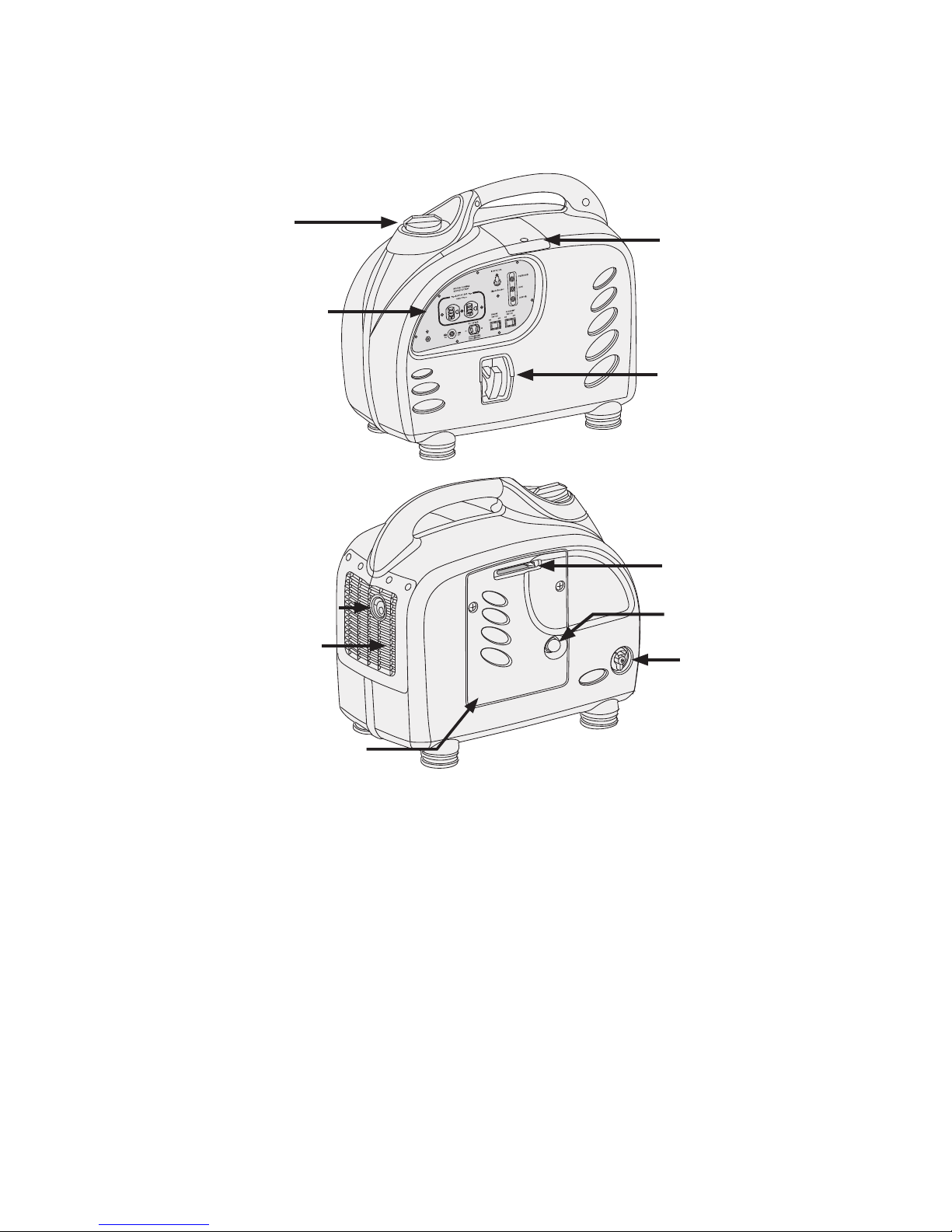
1.1 ACX2000i Generator .............................................................................................................................................7
1.2 ACX2000i Generator Accessories..........................................................................................................................7
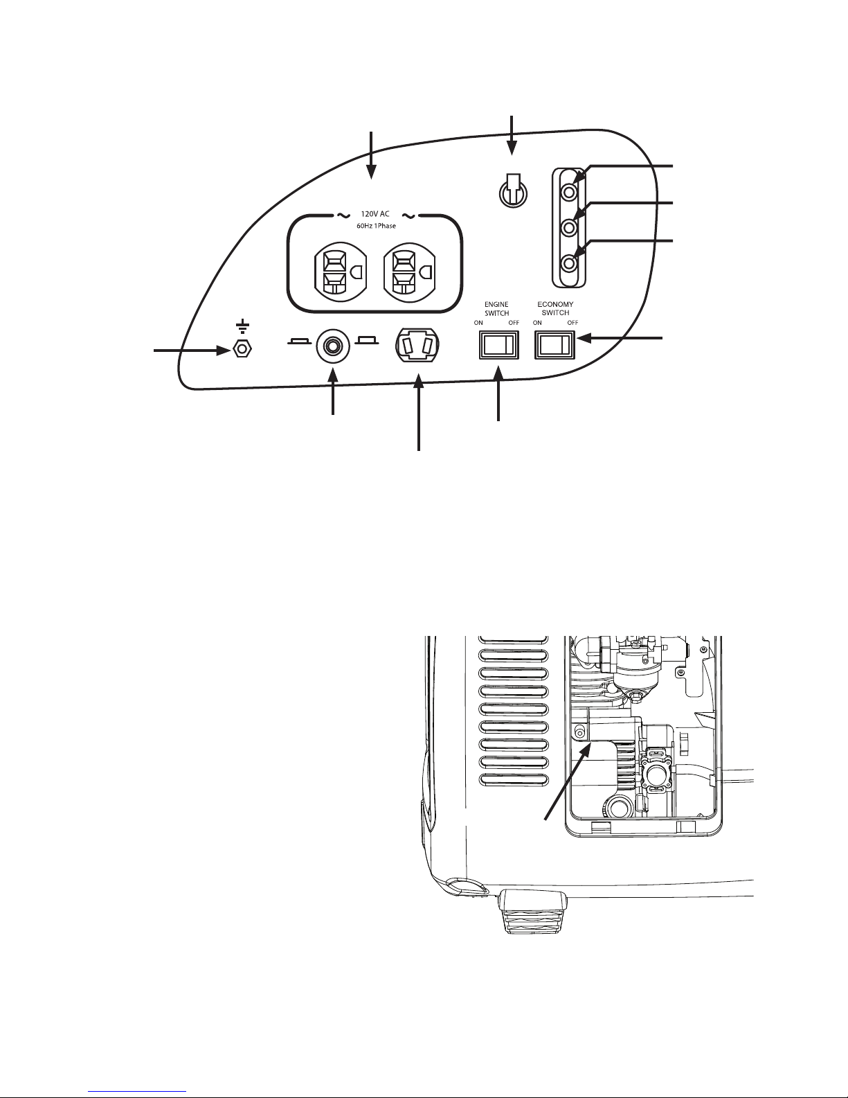
1.3 Control Panel..........................................................................................................................................................8
1.4 Serial Number/Bar Code Identication Location ....................................................................................................8
2.0 Operation..........................................................................................................................................................................9
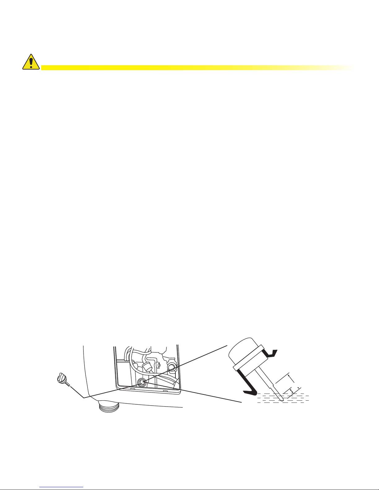
2.1 Oil Level .................................................................................................................................................................9
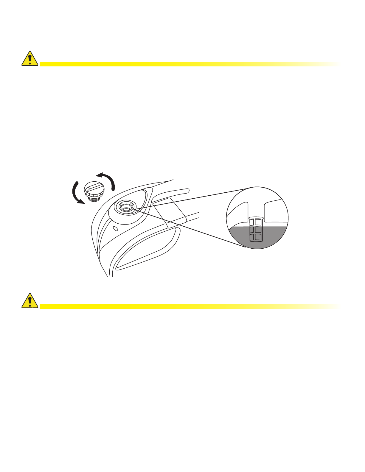
2.2 Fuel Level.............................................................................................................................................................10
2.3 Air Cleaner ........................................................................................................................................................... 11
2.4 Starting the Engine...............................................................................................................................................12
2.5 High Altitude Operation ........................................................................................................................................13
2.6 Operating at Extreme Temperatures ....................................................................................................................13
2.7 Using the Generator.............................................................................................................................................14
2.8 AC Application......................................................................................................................................................15
2.9 Output and Overload LEDs ..................................................................................................................................16
2.10 DC Application......................................................................................................................................................17
2.11 Low Oil Alarm System ..........................................................................................................................................19
2.12 Economy Switch...................................................................................................................................................19
2.13 Stopping the Engine .............................................................................................................................................20
3.0 Maintenance.................................................................................................................................................................21
3.1 Emission Control System .....................................................................................................................................21
3.2 Maintenance Schedule.........................................................................................................................................22
3.3 Changing Oil.........................................................................................................................................................23
3.4 Servicing the Air Cleaner......................................................................................................................................24
3.5 Spark Plug Maintenance ......................................................................................................................................25
3.6 Spark Arrestor Maintenance.................................................................................................................................27
4.0 Transporting And Storage.............................................................................................................................................28
4.1 Transporting the Generator ..................................................................................................................................28
4.2 Short Term Storage of the Generator ...................................................................................................................28
4.3 Infrequent Use......................................................................................................................................................28
4.4 Exercising the Generator......................................................................................................................................29
5.0 Troubleshooting............................................................................................................................................................30
5.1 Engine will not start ..............................................................................................................................................30
5.2 Equipment does not Operate ...............................................................................................................................31
5.3 No Output at the DC Receptacle..........................................................................................................................31
6.0 Specications ...............................................................................................................................................................32
7.0 Warranty And Consumer Information ...........................................................................................................................33
Appendix A – Emission Control System Warranty................................................................................................................35
Appendix B – Emission Control System...............................................................................................................................36
Appendix C – Safety And Charging Instructions...................................................................................................................36

5041-036-B000-001, Rev. A (07/2013)
Figures & Tables
Figure 1-1, Generator Controls............................................................................................................................. 7
Figure 1-2, Control Panel Component Identication............................................................................................. 8
Figure 1-3, Serial Number Location...................................................................................................................... 8
Figure 1-4, Checking Engine Oil........................................................................................................................... 9
Figure 2-1, Fuel Level......................................................................................................................................... 10
Figure 2-2, Air Filter Components....................................................................................................................... 11
Figure 2-3, Starting the Engine........................................................................................................................... 12
Figure 2-4, Temperature Range and OilTypes ................................................................................................... 13
Figure 2-5, Grounding the Generator ................................................................................................................. 14
Figure 2-6, Control Panel AC Applications Components.................................................................................... 15
Figure 2-7, Overload LED Location.................................................................................................................... 16
Figure 2-8, Battery Charging .............................................................................................................................. 17
Figure 2-9, Circuit Breaker Location................................................................................................................... 18
Figure 2-10, Low Oil Alarm LED Location .......................................................................................................... 19
Figure 2-11, Economy Switch Location .............................................................................................................. 19
Figure 2-12, Engine Switch Location.................................................................................................................. 20
Figure 3-1, Example of Emission Control Tag .................................................................................................... 22
Figure 3-2, Temperature Range and OilTypes ................................................................................................... 23
Figure 3-3, Changing Engine Oil ........................................................................................................................ 23
Figure 3-4, Cleaning the Air Filter....................................................................................................................... 24
Figure 3-5, Accessing the Spark Plug ................................................................................................................ 25
Figure 3-6, Gapping the Spark Plug................................................................................................................... 26
Figure 3-7, Maintaining the Spark Arrester......................................................................................................... 27
Figure 4-1, Cranking Motor to Distribute Oil in Cylinder..................................................................................... 29
Table 3-1, ACX2000i Maintenance Schedule ..................................................................................................... 22
Table 6-1, ACX2000i Generator Specications .................................................................................................. 32

6041-036-B000-001, Rev. A (07/2013)
ACX2000i Safety Instructions
Alpha considers customer safety and satisfaction its most important priority. To reduce the risk of injury or death and to
ensure continual safe operation of this product, read this manual entirely and follow all safety information therein.
• The mufer is hot during and after operation for a few minutes.
• Do not to touch the mufer while it is hot.
• Keep away from moving parts while the generator is running.
WARNING! INJURY HAZARDS
• Generator produces poisonous carbon monoxide. Never run the generator in an enclosed
area.
• Gasoline is extremely ammable and explosive under certain conditions.
• Refuel in a well ventilated area with the engine stopped.
• Keep away from cigarette smoke and sparks when refueling the generator.
• Wipe up spilled gasoline immediately.
• Let the engine cool before storing the generator indoors.
WARNING! FUMES & FIRE HAZARD
Generators are a potential source of electrical shocks when misused; do NOT operate wet
conditions.
WARNING! ELECTRICAL HAZARD
• Do not operate the generator in rain or snow, and do not let it get wet.
• Do not modify the enclosure of this generator.
• To avoid equipment damage, always check the oil and fuel level and air lter before you start the engine.
• Place the generator at least 3 ft (1 m) away from buildings during operation.
• Operate the generator on a level surface. If the generator is tilted, fuel spillage may result.
• Know how to stop the generator quickly and understand operation of all controls. Never permit anyone to
operate the generator without proper instructions.
CAUTION!
Read the entire manual and review all the drawings and illustrations contained in this manual before proceeding. If there
is any question regarding the safe installation or operation of the product or its components, contact Alpha Technologies
or the nearest Alpha representative. Save this document for future reference.

7041-036-B000-001, Rev. A (07/2013)
1.0 Introduction
1.1 ACX2000i Generator
1.2 ACX2000i Generator Accessories
The following additional items are included with the generator. Keep all accessories in a convenient
location for future use or reference.
• Battery Charge Kit
• Oil Jug
• Oil Drain Pipe
• Quick Start Guide
• Screwdriver
• Spare Spark Plug
• Spark Plug Wrench
Spark Plug
Access Cover
Choke Lever
Maintenance Panel
Exhaust Grill
Spark Arrestor
Fuel Valve
Primer Bulb
Gas Cap
Control Panel
Starter Grip
Figure 1-1, Generator Controls

8041-036-B000-001, Rev. A (07/2013)
1.3 Control Panel
1.4 Serial Number/Bar Code Identication Location
The generator bar code number and the engine serial number identify your particular unit and are
necessary when ordering parts and accessories. These two numbers are used by the dealer and The
Coast Distribution System, Inc. for warranty administration and must be supplied before any work can be
done.
The engine serial number can be
found stamped on the engine block
above oil dipstick. It is visible when the
maintenance panel is removed.
The bar code number label is found in
three locations:
• On the side of the generator near the
fuel valve.
• On the back of this manual.
The BCN number is on the foil label on
the shipping carton. Please record this
information in a convenient location for
reference.
Circuit Breaker
120V AC 20A
NEUTRAL FLOATING
NEUTRE FLOTTANT
DC 12V 8.3A
SYSTEM FLOATING
SYSTÈME FLOTTANT
OFFON
OVERLOAD
RUN
LOW OIL
Overload LED (Red)
Run LED (Green)
Low Oil Alarm (Red)
Economy Switch
Engine Switch
Battery Charge
Receptacle
Battery Charge
Circuit Breaker
Ground
Terminal
120 V 20A
Duplex Receptacle
120 V 20A
Circuit Breaker
Figure 1-2, Control Panel Component Identication
Figure 1-3, Serial Number Location
Serial Number
11085603

9041-036-B000-001, Rev. A (07/2013)
2.0 Operation
2.1 Oil Level
• Check the oil level before every operation.
• Check the oil level with the generator on a level surface with the engine stopped.
• Do not use non-detergent oil or 2-stroke engine oil. It will void the warranty and will shorten the engine’s service
life.
• Use a high-detergent, premium quality, 4-stroke engine oil, certied to meet or exceed U.S. automobile
manufacturer’s requirements for API Service Classication SG/SF.
• Change the oil in a new engine between the rst 4 to 6 hours of operation to remove manufacturing debris and
contamination.
• Use SAE 15W-40 viscosity oil unless operating at ambient temperatures below 32° F (0° C). For temperatures
below 32° F, use SAE 0W-40 viscosity oil. Refer to the Operating at extreme temperatures section for more
information.
• Synthetic oil is approved for use in Alpha generators generally, and is recommended when operating the
generator in temperatures below 32° F. Use synthetic oil to ll the oil well of the generator, and use it for
subsequent oil changes.
• Running the engine with insufcient oil can cause serious engine damage.
• The Low Oil Alarm System will automatically stop the engine before the oil level falls below a safe limit.
CAUTION!
Required Tools
• Screwdriver
• Clean rag
Engine oil capacity: 15.6 oz (0.98 pt) / 460 ml.
1. Loosen the cover screws and remove the maintenance cover.
2. Remove the dipstick, wipe it with a clean rag and reinsert it into the ller neck, screwing it down
completely.
3. Remove the dipstick again and check the oil level.
4. If the oil level is at or below the lower level of the dipstick, rell with the recommended oil up to the top
of the upper level marking. Do not overll.
5. Reinsert the dipstick and be sure to screw it down until it is tight.
Upper Level
Dipstick
Oil Fill Hole
Lower Level
Figure 1-4, Checking Engine Oil

10 041-036-B000-001, Rev. A (07/2013)
2.2 Checking the Fuel Level
• Use a fuel stabilizer, such as STA-BIL®, to help prevent fuel oxidation (breakdown) and the formation of gum and
varnish, and to inhibit corrosion in the fuel system and carburetor.
• Fuel system damage or engine performance problems resulting from the use of fuels that contain an improper
alcohol blend, or by adding oil to the fuel, are not covered under warranty.
• Before buying fuel from an unfamiliar station, determine if the fuel contains ethanol and if it does, conrm the
type and percentage of ethanol used. If any undesirable operating symptoms appear while using a gasoline that
contains ethanol, replace it with a gasoline that has the proper blend.
CAUTION!
Use automotive unleaded regular gasoline only. Fuel tank capacity: 1.4 gal (5.3 Liters).
1. If the fuel level is low, rell to the top of the fuel strainer.
2. After refueling, tighten the fuel ller cap securely.
For gasoline containing alternate fuels do not use a blend that contains more than 10% ethanol. Do not use
gasoline containing methanol. An octane rating of 87 or higher is recommended. Fuel system damage or engine
performance problems resulting from the use of fuels that contain an improper alcohol blend are not
covered under warranty.
CAUTION!
2.0 Operation
Gas Cap
Fuel Strainer
Fuel
Figure 2-1, Fuel Level
Table des matières
Autres manuels AlphaGen Générateur portable


