
ALLIANCE ALLPH9Kw-INV Manuel utilisateur
Alliance Domestic Inverter
Pool Heat Pump
Installation & Operation Manual
Models: ALLPH9Kw-INV
ALLPH12Kw–INV
ALLPH16Kw–INV
ALLPH19Kw–INV
Thank you very much for purchasing our product.
Before using your heat pump, please read this manual
carefully and keep if for future reference.
The manufacturers of Alliance Heat Pumps employ over 300 senior engineers and operate
31 approved test laboratories, guaranteeing the innovation and high quality of Alliance products.

Contents
Preface .............................................................................................................................................. 1
• Features 1
• About heat pumps 2
• Sizing guide table 2
• Weight / Dimensions 2
Specifications – ALLPH90R410-INV / ALLPH120R410-INV .............................................................. 2
Specifications – ALLPH160R410-INV / ALLPH190R410-INV ............................................................ 3
Dimensions ........................................................................................................................................ 5
Installation and connection .............................................................................................................. 5
• Heat pump location 5
• How close to your pool 5
• Installation illustration 6
• Installation of check valve 6
Electrical wiring ................................................................................................................................ 7
Initial start-up of unit ....................................................................................................................... 8
Condensation .................................................................................................................................... 8
Controller operation .................................................................................................................... 9-16
Error code list ............................................................................................................................ 17-18
PC Board wiring diagram ............................................................................................................... 19
Maintenance and inspection............................................................................................................ 20
Appendix ......................................................................................................................................... 21
Warranty .................................................................................................................................... 22-24
Contact Information ........................................................................................................................ 25
N.B: This Installation Manual is the property of Alliance Heat Pumps, and all rights of copyright are reserved. It may not be
reproduced or used for any other purpose without written permission from Alliance. In the interests of product
improvement, Alliance reserves the right to change specifications without prior notice.

Preface
In order to provide our customers with quality, reliability and versatility, this product has been made
to strict production standards. This manual includes all the necessary information about installation,
debugging, discharging and maintenance. Please read this manual carefully before you open or
maintain the unit. The manufacture of this product will not be held responsible if someone is injured
or the unit is damaged, as a result of improper installation, debugging, or unnecessary maintenance.
It is vital that the instructions within this manual are adhered to at all times. The unit must be
installed by qualified personnel.
The unit can only be repaired by qualified personnel or an authorized dealer.
Maintenance and operation must be carried out according to the recommended time and frequency,
as stated in this manual.
Use genuine standard spare parts only. Failure to comply with these recommendations will invalidate the
warranty.
Swimming Pool Heat Pump Unit heats the swimming pool water and keeps the temperature constant.
Our heat pump has the following characteristics:
• Durable
The heat exchanger is made of PVC & Titanium tube which can withstand prolonged exposure to
swimming pool water.
• Quiet operation
The unit comprises an efficient inverter compressor and fan motor, which guarantees its quiet
operation.
• Advanced control
The unit includes micro-computer controlling, allowing all operation parameters to be set. Operation
status can be displayed on the LCD wired controller.
1

Specifications
Performance data
UNIT ALLPH90R410 - INV ALLPH120R410 - INV
Operating air temperature °C -15 to 43
Heating Capacity kW 2.2 – 9.0 3.77 – 16.9
Consumed power kW 0.16 – 1.60 0.3 – 3.02
COP 13.75 – 5.63 12.57 – 5.63
Power supply 230V~/ 50Hz
Nominal Heating Capacity kW 4.29 9,7
Nominal power input kW 0.74 1.38
Max power input kW 1.97 3.2
Nominal Running current
A
3.35
6
Current range
A
1.29 – 6.86 1.3 – 13.1
Max Current
A
8.62 13.96
Compressor quantity
1
1
Compressor type Rotary Rotary
Refrigerant R410a
Fan quantity
1
1
Fan power input
W
100
120
Fan rotary speed RPM 500 - 750 600 - 750
Fan direction Horizontal Horizontal
Noise dB(A) 40 44
Water connection mm 50 50
Nominal water flow m3/h 2.0 5.3
Water pressure drop (max)
kPa
4.0
5
Unit net dimensions (L*W*H) mm 1003*396*767 1117*430*868
Unit shipping dimensions (L*W*H) mm 1130 *460*780 1210*510*880
Net weight kg 50 77
Shipping weight kg 60 90
Test conditions - Air 27°C / Water 26°C / Humidity 80%
2

Specifications
Performance data
UNIT
ALLPH160R410 - INV ALLPH190R410 - INV
Operating air temperature °C -15 to 43
Heating Capacity kW 3.77 – 16.9 4.6 – 19.5
Consumed power kW 0.3 – 3.02 0.37 – 3.94
COP 12.57 – 5.63 12.43 – 4.95
Power supply 230V~/ 50Hz
Nominal Heating Capacity kW 9,7 11.5
Nominal power input kW 1.38 1.72
Max power input kW 3.2 4.88
Nominal Running current
A
6
7.5
Current range
A
1.3 – 13.1 1.6 – 17.1
Max Current
A
13.96 21.17
Compressor quantity
1 1
Compressor type Rotary Rotary
Refrigerant R410A
Fan quantity
1 1
Fan power input
W
120 120
Fan rotary speed RPM 600 - 750 600 - 900
Fan direction Horizontal Horizontal
Noise dB(A) 44 45
Water connection mm 50 50
Nominal water flow m3/h 5.3 6.6
Water pressure drop (max) kPa
5 6
Unit net dimensions (L*W*H) mm 1117*430*868 1117*430*868
Unit shipping dimensions (L*W*H) mm 1210*510*880 1210*510*880
Net weight kg 77 82
Shipping weight kg 90 95
Test conditions - Air 27°C / Water 26°C / Humidity 80%
3

L
1117
mm
H 868 mm
W 447 mm
Dimensions
Alliance Inverter 9/12kw
Alliance Inverter 16 / 19kw
Alliance Inverter
16Kw
Alliance Inverter
19Kw
A 400 470
L
1003
mm
H 767 mm
W 410 mm
3
4

Installation and Connection
Heat Pump Location
The unit will perform well in any outdoor location provided that the following three factors are
presented:
1. Fresh Air - 2. Electricity - 3. Pool filter piping
The unit may be installed virtually anywhere outdoors. For indoor pools please consult the supplier.
Unlike a gas heater, it has no draft or pilot light problem in a windy area.
DO NOT place the unit in an enclosed area with a limited air volume, where the units discharge
air will be re-circulated.
DO NOT place the unit close to bushes or shrubs which can block air inlet / outlet. These locations
deny the unit of a continuous source of fresh air which reduces its efficiency and may prevent
adequate heat delivery.
How Close To Your Pool?
Normally, the pool heat pump is installed within 7.5 meters of the pool. The longer the distance from the
pool, the greater the heat loss from the piping. For the most part, the piping is buried. Therefore, the heat
loss is minimal for runs of up to15 meters(15 meters to and from the pump = 30 meters total), unless the
ground is wet or the water table is high. A very rough estimate of heat loss per 30 meters is 0.6 kW-
hour,(2000BTU) for every 5°C difference in temperature between the pool water and the ground
surrounding the pipe, which translates to about 3% to 5% increase in run time.
5
Installation illustration
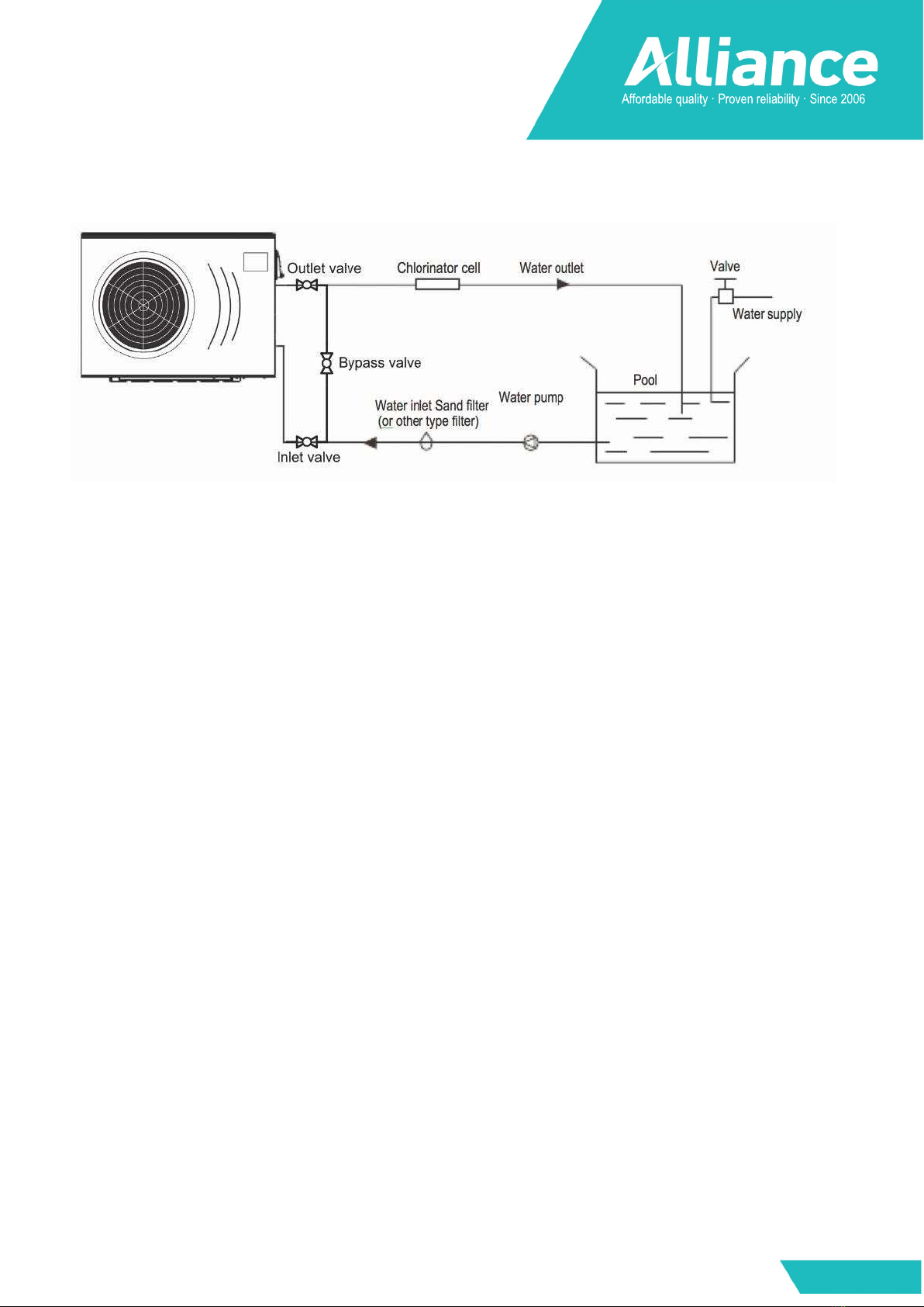
Remarks:
The factory only provides the heat pump. Other parts, including a by-pass are to be provided by the
user or installer.
Attention:
Please take the following steps when installing the heat pump:
1.
Each addition of chemicals has to be performed through the conduits located AFTER the heat pump.
2.
Install a by-pass for easy maintenance
3.
Always place the heat pump on a solid base and use the supplied silent blocks in order to avoid
vibrations and noise.
4.
Always keep the heat pump in upright position. If the unit has been tilted, you should wait for at least
24 hours before turning it on.
Installation of a check valve
When using automatic chlorine and pH dosage systems, it is of extremely import to protect
the heat pump from high concentrations of these chemicals that could corrode the heat exchanger Therefore,
such systems should add the chemicals in the conduits located DOWNSTREAM of the heat pump and it is
recommended to install a check-valve in order to prevent backflow when there is no water circulation.
Damage to the heat pump caused by disregarding any of these recommendations will invalidate the
warranty.
6

Electrical Wiring
Important - Although the heat pump is electrically isolated from the rest of the unit, this only
prevents the passage of electricity to or from the pool water. Grounding the unit is still
required to protect yourself from short circuits inside the unit. Make for adequate ground
connection.
Check if the electrical mains voltage corresponds with the operating voltage of the heat pump prior to
hooking up the unit.
It is recommended to use a separate fuse (C-curve) as well as adequate wiring (see table below). Connect
the electrical wires with the terminal block labelled ‘TO POWER SUPPLY’.
Next to this connection, there is a second terminal block labelled ‘TO PUMP’, to which the pool pump
(max. 5A/240V) or an electrical relay for a filtration pump can be connected. This connection makes it
possible to control the pool pump operation with the heat pump.
However, we do not recommend that you wire the pool circulation pump to the heat pump. Run
separate power supplies to the heat pump and the pool circulation pump. This allows the pool
circulation pump to be put on a time clock and operated for the required time to give adequate
filtration for the pool and also the pool circulation pump can be manually operated when
required to backwash the filter etc.
Model Voltage (V) Fuse (C-curve) Max current (A)
Cable section*
ALLPH90R410 - INV 220-240V 20 8.62 2.5 mm2
ALLPH120R410 - INV 220-240V 20 13 2.5 mm2
ALLPH160R410 - INV 220-240V 20 13.96 2.5 mm2
ALLPH190R410 - INV 220-240V 32 21.17 4 mm2
* For a maximum cable length of 50m
7

Initial startup of the Unit
NOTE- In order for the unit to heat the pool or spa, the filter pump must be running to circulate
water through the heat exchanger.
Start up Procedure - After installation is completed, you should follow these steps:
1. Turn on your pool pump. Check for water leaks and verify flow to and from the pool.
2. Turn on the electrical power supply to the heat pump, then press the key ON/OFF on the wire
controller. It should start in several seconds.
3. After running a few minutes make sure the air leaving the fan opening of the unit is cooler (between
5-10°C)
4. With the unit operating turn the pool pump off. The unit should also turn off automatically,
5. Allow the unit and pool pump to run 24 hours per day until desired pool water temperature is reached.
When the desired pool water temperature reaches the setting, the unit just shuts off. The unit will now
automatically restart (as long as your pool pump is running) when the pool temperature drops more
than 2°C below set temperature.
Time Delay- The unit is equipped with a 3 minute built-in solid state restart delay included to protect
control circuit components and to eliminate restart cycling and contactor chatter.
This time delay will automatically restart the unit approximately 3 minutes after each control circuit
interruption. Even a brief power interruption will activate the solid state 3 minute restart delay and
prevent the unit from starting until the 3 minute countdown is completed. Power interruptions during
the delay period will have no effect on the 3 minute countdown.
Condensation
Since the Heat pump cools down the air about 5°C, water may condense on the fins of the evaporator. If
the relative humidity is very high, this could be as much as several litres an hour. The water will run down
the fins into the base pan and drain out through the barbed plastic condensation drain fitting on the side
of the base pan.
This fitting is designed to accept 20mm clear vinyl tubing which can be pushed on by hand and run to
a suitable drain. It is easy to mistake the condensation for a water leak inside the unit.
TIP:
A quick way to verify that the water is condensation is to shut off the unit and keep the pool pump
running. If the water stops running out of the base pan, it is condensation. AN EVEN QUICKER WAY IS
TO TEST THE DRAIN WATER FOR CHLORINE - if there is no chlorine present, then it’s condensation.
8
Ce manuel convient aux modèles suivants
5
Table des matières
Autres manuels ALLIANCE Pompe à chaleur


Manuels Pompe à chaleur populaires d'autres marques


Mitsubishi Electric
Mitsubishi Electric PUZ-SWM60VAA Manuel utilisateur

Dimplex
Dimplex LI 16I-TUR Guide de l'utilisateur

Carrier
Carrier WSHP Open v3 Guide de configuration rapide

TGM
TGM CTV14CN018A Manuel utilisateur

Carrier
Carrier 38MGQ Series Manuel utilisateur

Kokido
Kokido K2O K880BX/EU Guide de dépannage


