ALBERTI TURBODRILL Manuel utilisateur

INSTRUCTION
BOOK
TURBODRILL /
TURBOFLEX
TURBODRILL / TURBOFLEX
ANGLE HEADS

TABLE OF CONTENTS
SafetyRecommendations............................................................
Tool Run-in..................................................................................
Determining the Retaining Block Thickness................................
Mounting the Retaining Block.....................................................
Retaining Block Mounting Errors.................................................
Radial Positioning of Angle Heads Around the Z Axis................
Re-setting the Graduation Ring (if applicable)............................
Air / Oil Regulator Installation.....................................................
Air / Oil Regulator Operation......................................................
Air / Oil Regulator Picture Diagram............................................
Troubleshooting.........................................................................
IC-300 / KC-300 Cutting Tool & Collet Instructions...................
RA-100 / RA-200 Cutting Tool & Collet Instructions....................
Turbodrill (30 Taper) / NSK Tooling Chart..................................
Turboex / NSK Tooling Chart....................................................
Collet Chart.................................................................................
Warranty......................................................................................
Parts and Service........................................................................
Page
1
2
2
4
5
6
6
7
7
8
9
10
11
12
14
15
17
17
All information in this manual is subject to change without notice.
Please contact Koma for more information.

SAFETY RECOMMENDATIONS
- Do not touch or hold anything near the head when it is running or
rotating in any manner.
- When the angle head is mounted in the machine spindle or tool
magazine, be sure it is not hot.
- When the head is to be used, ensure the input taper is correctly mated
to the machine spindle, the arrester arm and block are engaged
properly, and that the cutting tool is clamped tightly before activating the
air circuit to start the spindle rotating.
- Make sure the cutting tool is designed to run in the same direction as the
NSK air motor (R = Right and L = Left).
- Use caution during set-up of the head as personal injury may occur if
dropped or mishandled.
AUTOMATIC TOOL CHANGER
- Check the Automatic Tool Changer (ATC) speed and manually check
loading and unloading of the head into the machine spindle prior to
running in automatic cycle.
- Routinely check the stopper block to be sure it is clean and free of chips.
NSK CARTRIDGE INFORMATION
- The threaded input of the cartridge is not qualied to the output. To
ensure accurate positioning, install the NSK cartridge into the head,
insert the ground mandrel in the collet and indicate to conrm / adjust
the position.
- The NSK cartridges are not designed to withstand high axial and
radial thrust.
- A weekly visual inspection and cleaning of the head is recommended.
- Be sure to check the oil level on the oil lubricator periodically.
- Always use cutting tools with precision ground shanks to ensure proper
tightening and minimal tool runout.
- For extended reach machining, a CN-01 extension spacer may be used.
1
Koma Precision Inc. • 20 Thompson Road, East Windsor, CT 06088
1-800-249-KOMA Fax: 860-623-4132
www.komaprecision.com • [email protected]

2
TOOL RUN-IN
For new heads or units that have not been used for over (1) month, the
motor speed should be increased gradually. Increase the air pressure
slowly using the pressure adjustment knob (refer to drawing on page 8),
over a period of 15-20 minutes, until the unit is at maximum operating
speed.
DETERMINING THE RETAINING BLOCK THICKNESS
Use the following procedure to correctly to locate the retaining block , with
a 3mm space between end of pin and bottom of 18mm ID in the block.
1. Mount the angle head in the machine tool spindle and measure
dimension X. (Fig 1a)
2. Remove the angle head from the machine tool spindle and slip the
retaining block on the arrester pin.
3. Measure dimension W. (Fig 1b)
4a. If dimension Wis less than dimension X, prepare a shim with
thickness as below:
S= (X - W + 3mm)+0.5mm
4b. If dimension Wis greater than dimension X, machine the thickness
of the retaining block as below:
W= (X + 3mm)+0.5mm
Koma Precision Inc. • 20 Thompson Road, East Windsor, CT 06088
1-800-249-KOMA Fax: 860-623-4132
www.komaprecision.com • [email protected]

3
Koma Precision Inc. • 20 Thompson Road, East Windsor, CT 06088
1-800-249-KOMA Fax: 860-623-4132
www.komaprecision.com • [email protected]
DETERMINING THE RETAINING BLOCK THICKNESS
X
Arrester pin
W
S
Arrester pin
Retaining
block
Shim
(if required)
Arrester pin
Retaining block
gap between
bottom of
arrestor pin and
retaining block
Alberti head shown in
machine tool spindle,
ready to run.
3mm (.118”)
Shim (if required)
10
0
360
Fig. 1a
Fig. 2
Fig. 1b
Standard Stopper Block

4Koma Precision Inc. • 20 Thompson Road, East Windsor, CT 06088
1-800-249-KOMA Fax: 860-623-4132
www.komaprecision.com • [email protected]
MOUNTING RETAINING BLOCK •ORIENTATION OF ARBOR
To locate the retaining block at the correct distance from the spindle center
line and to assure the correct orientation of the arbor with reference to the
arrester pin, use the following procedure:
1. Secure the retaining block by slightly tightening the mounting screws.
2. Loosen set screws 06 one turn and fit the head into the machine spindle
(make sure that the arrester pin slips in easily).
3. Fully tighten the mounting screws of the retaining block.
4. Remove and carefully clean set screws 06.
5. Check whether the collet chuck is properly oriented for tool change.
6. Put a few drops of Loctite 242e or equivalent on the threads of set
screws 06 then tighten set screws 06 on orientation ring 10.
7. Unload and load the head several times with the automatic tool changer
to check for correct operation.
8. Dowel the retaining block to the machine tool to prevent any shifting.
ATTENTION: During the first automatic tool change, make sure that the
angle head does not interfere with other components of the system.
01
06
10
06
c

5
Koma Precision Inc. • 20 Thompson Road, East Windsor, CT 06088
1-800-249-KOMA Fax: 860-623-4132
www.komaprecision.com • [email protected]
RETAINING BLOCK MOUNTING ERRORS
If the distance from the machine tool spindle centerline and the centerline
of the retaining block bushing is not correct, the arrester pin on the angle
head will not seat properly in the retaining block bushing. This will result in
the conditions shown below, causing damage to the angle head bearings.
retaining block
mounted too far
from spindle centerline
retaining block
mounted too close
to spindle centerline
cc
Retaining
block bushing
Arrester pin
Retaining
block
Retaining
block bushing
Arrester pin
Retaining
block
If the arrester pin is completely compressed against the bottom of the
retaining block, the shank of the angle head will not seat properly in the
machine tool spindle, causing damage to the angle head bearings. The
3mm/.118” gap between the bottom of the arrester pin and the retaining
block must be met in order for the angle head shank to seat properly in the
machine tool spindle (see page 3).
0
Wrong!
Correct! 3mm
(.118”)
Arrester pin
Retaining block

6Koma Precision Inc. • 20 Thompson Road, East Windsor, CT 06088
1-800-249-KOMA Fax: 860-623-4132
www.komaprecision.com • [email protected]
RADIAL POSITIONING OF TURBOFLEX ANGLE HEADS
Applies to: RA-200, RA-100, RA-271E,
RA-151E, & RAX-271E NSK Cartridges.
To position the angle head body radially
around the Z axis of the machine tool,
use the following procedure:
1. Mount the angle head on the machine.
2. Loosen screws 08.
3. Rotate angle head body 30 to the
required position.
3. Clamp a ground mandrel in the collet
of the NSK output and use a dial gauge
with a flat point to check for precise
position.
5. Tighten screws 08. Suggested
screw torque 8-10 Nm (5.9-7.4 ft.lbs.).
Do not use an extension for the
Allen wrench.
RE-SETTING THE GRADUATION RING (IF APPLICABLE)
Applies to: RA-200, RA-100, RA-271E,
RA-151E, & RAX-271E NSK Cartridges.
When the head is correctly oriented
and positioned, graduated ring 12 can
be reset. Loosen screw 13 and rotate
the ring until the zero coincides with the
reference notch in the indexing ange.
Re-tighten screw 13.
13
12
09
30
08

7
AIR / OIL REGULATOR (#AL40-N02-3Z) INSTALLATION
Refer to picture diagram on page 8 for these instruction.
- Mount this unit on the machine tool, in a convenient location with easy
access for servicing (maintaining the proper oil level and draining of
the water).
- Fill oil reservoir using ISO-VG15 (paraffin based) oil or equivalent.
- Connect the air input line to the input side of the unit. (Be sure shut-off
valve is “OFF”).
NOTE: It is recommended that a Quick Disconnect be used for the input
air line!
- Connect the air output line to the stopper block (1/8” NPT) or thru spindle
circuit. (Stopper block set-up is most common).
- Adjust the air pressure using the air pressure regulator adjustment knob.
Recommended pressure is 58 - 87 psi (0.4 - 0.6 MPa).
- Open the shut-off valve and adjust the oil drip rate using the oil lubricator
adjustment knob to 1-3 drops/min. (This is a rough setting and will need
to be fine-tuned once the head is connected).
AIR / OIL REGULATOR (#AL40-N02-3Z) OPERATION
Refer to picture diagram on page 8 for these instruction.
- Oil Volume: Check the oil reservoir at least once a week. Use caution to
avoid under and over filling of the reservoir as it can cause the oil delivery
rate to vary.
CAUTION: Be sure to disconnect the air input line and check for zero
pressure at the gage, prior to opening the oil filler cap!
- Water in the Air Filter: Drain the water from the moisture reservoir by
unscrewing the black cap at the bottom of the reservoir bowl. A drain
hose may be installed on the bottom of the reservoir by depressing the
red button on the end of the black cap and inserting the correct diameter
hose into it.
- Adjusting the Oil Drip Rate: Run the head at the desired air pressure/
RPM and adjust the oil drip rate to the recommended amount by turning
the lubricator adjustment knob. Turn the CCW to increase the drip rate
and CW to decrease the drip rate.
- Remove Oil & Moisture Regularly: Remove and replace the oil in the
reservoir once a month to ensure a pure lubricant for the motor. Moisture
may collect and mix with the oil in the reservoir causing premature
damage to the motor. The easiest method to remove the oil and clean the
bowl is to remove it from the reservoir. Depress the release buttom in the
downward direction and rotate the bowl for removal.
- Oil Grade: ISO VG-15 (paraffin based oil) is recommended.

8Koma Precision Inc. • 20 Thompson Road, East Windsor, CT 06088
1-800-249-KOMA Fax: 860-623-4132
www.komaprecision.com • [email protected]
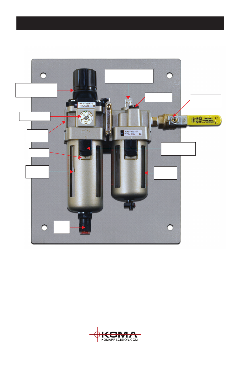
AIR / OIL LUBRICATOR DIAGRAM
AL40-N02-3Z Air / Oil Lubricator w/ Shut-Off Valve
Pressure Regulator
Adjustment Knob
Pressure Gage
Air Input
(1/4” NPT)
Air Filter
Moisture
Reservoir
Water
Drain
Oil
Reservoir
Bowl Reservoir
Release Buttons
Air Output with
Shut-Off Valve
Oil Filler Cap
Oil Lubricator Sight Glass
& Adjustment Knob
Ce manuel convient aux modèles suivants
1
Table des matières
Autres manuels ALBERTI Scrubber