
Aktakom ACM-3192 Manuel utilisateur
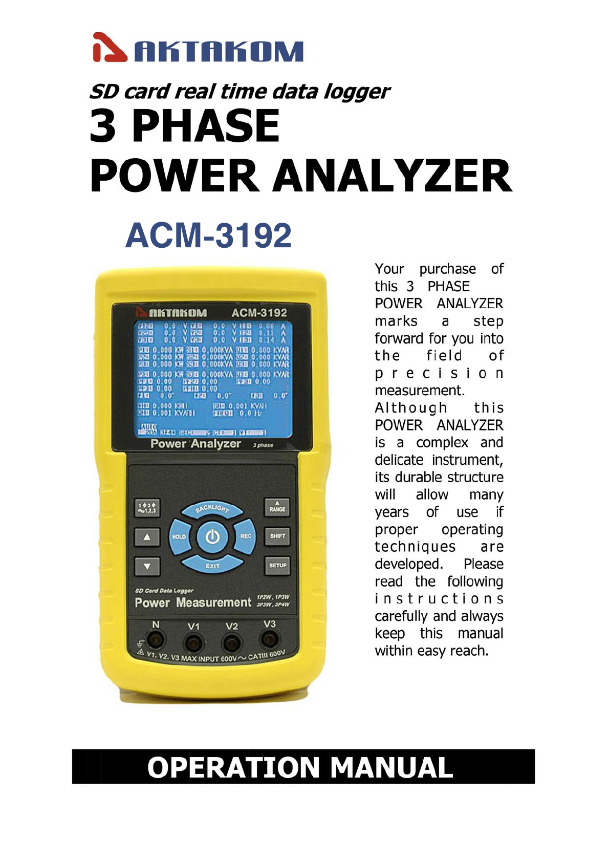
АСМ-3192
Caution Symbol
Caution :
* Risk of electric shock !
* During the measurement,
do not open the cabinet.
Caution :
* Do not apply the overload
voltage, current to the input
terminal !
* Remove test leads before open
the battery cover !
* Cleaning - Only use the dry
cloth to clean the plastic case !
Environment Conditions
* Installation Categories III 600V.
* Pollution Degree 2.
* Altitude up to 2000 meters.
* Indoor use.
* Relative humidity 80% max.
www.tmatlantic.com

TABLE OF CONTENTS
1. FEATURES................................................................
.
1
2. SPECIFICATIONS...................................................... 2
2-1 General Specifications......................................... 2
2-2 Electrical Specifications....................................... 4
3. FRONT PANEL DESCRIPTION..................................... 8
4. MEASURING PREPARATION ......................................
.
10
4-1 The original screen.............................................. 10
4-2 Entry the measurement Screen............................
.
10
4-3 The summary description of keyboard..................
.
12
4-4 SETUP KEY description.........................................13
4-5 Setting function description before measuring.......
.
14
5. MEASURING PROCEDURES .......................................
.
35
5-1 1Φ2W ( one phase by two wires )
measurement.....................................................
.
35
5-2 1Φ3W ( one phase by three wires )
measurement.....................................................
.
36
5-3 3Φ3W ( three phase by three wires )
measurement.....................................................
.
38
5-4 3Φ4W ( three phase by four wires )
measurement.....................................................
.
39
5-5 The CT and PT measurement............................... 41
5-6 ZERO adjustment for Watt Hour........................... 42
5-7 Data Logger function........................................... 43
5-8 Data Hold function............................................ 45
5-9 Backlight key.......................................................46
5-10 A ( Current ) Range key..................................... 46
5-11 LOWBAT screen.................................................48
5-12 Appendix 1........................................................49
6. MAINTENANCE..........................................................50
6-1 Cleaning.............................................................
.
50
6-2 Replacement of batteries ....................................
.
50
7. RS232 PC SERIAL INTERFACE.................................... 51
8. Download the saving data from the SD card to
the computer ( EXCEL software ) ..............................
.
53
9. PATENT.................................................................... 57
10. THE ADDRESS OF AFTER SERVICE CENTER .............58
www.tmatlantic.com

1. FEATURES
* Analysis for 3 phase multi-power system, 1P/2W,
1P/3W, 3P/3W, 3P/4W
* Voltage & Current are the True RMS value.
* True Power ( KW、MW、GW ) measurement.
* Apparent Power ( KVA、MVA、GVA ) measurement.
* Reactive Power ( KVAR MVAR、GVAR) measurement.
* Watt-Hour ( WH、SH、QH、PFH ).
* Power Factor( PF )、Phase Angle( Φ).
* Voltage measurement range : 10 to 600 ACV
* Current measurement range: 0.2A to 1200 ACA.
* Programmable CT ratio (1 to 600) and PT ratio (1 to 1000).
* ACV input impedance is 10 Mega ohms.
* Safety Standard : IEC 1010, CAT III 600V
* Built-in clock and Calendar, real time data record with
SD memory card , sampling time set from 2 to 7200
seconds. Just slot in the SD card into the computer, it
can down load the all the measured value with the
time information ( year/month/data/
hour/minute/second ) to the Excel directly, then user
can make the further data analysis by themselves.
* Complete set with 4 PCs Test Leads, 4 PCs Alligator
clips, 3 PCs Clamp Probe, AC to DC 9V adapter,
2 G SD memory card and Carrying bag.
* Computer data output, can cooperate with USB Cable
/USB-01 RS232 cable/UPCB-02 and Data Acquisition
software, SW-U811-WIN.
1
www.tmatlantic.com
2. SPECIFICATIONS
2-1 General Specifications:
Circuit Custom one-chip of microprocessor LSI
circuit
Display * LCD Size :
81.4 X 61 mm ( 3.2 X 2.4 inch )
* Dot Matrix LCD (320 X 240 pixels )
with back light.
Measurement * ACV
* ACA
* AC WATT ( True Power )
AC WATT( Apparent Power )
AC WATT( Reactive Power )
* Power factor
* Phase angle
* Frequency
Wire 1P/2W, 1P/3W, 3P/3W, 3P/4W.
connections
Voltage ranges 10 ACV to 600 ACV, auto range.
Current ranges 0.2 ACA to 1200 ACA,
auto range/manual range.
Safety IEC1010 CAT III 600 V.
standard
ACV input 10 Mega ohms.
impedance
Range select ACV Auto range.
ACA Auto range & manual range.
Clamp 40 Hz to 1 KHz.
frequency
response
Spec. tested 45 to 65 Hz.
frequency
Over load ACV 720 ACV rms
protection ACA 1300 ACA with clamp probe
CP-1200
2
www.tmatlantic.com
Over Indicator * LCD display show " OL ".
* The data save into the SD card will show
" 9999 " or " 999 "( overleap the decimal point ).
Under Indicator * LCD display show " UR ".
* The data save into the SD card will show
" 9999 " or " 999 "( overleap the decimal point ).
Data Hold Freeze the display reading.
Data Record SD Card Record.
Sampling Time Approx. 1 second.
Power ON/OFF Manual OFF by push button.
Real time * Real time data logger, saved the data
data logger into SD memory card and down load
the all the measured value with the
time information ( year/month/data/
hour/minute/second ) down load
to the Excel
* Integration time for data logger :
2 seconds to 7200 seconds, the during
of setting step are 2 seconds.
* Data error no. :
0.1% no. of total saved data typically.≦
Data Output RS232 computer serial interface :
USB/RS232 * Connect the optional USB cable
* Computer
USB-01 will get the USB plug.
interface
* Connect the optional RS232 cable
UPCB-02 will get the RS232
plug.
Operating 0 to 50 ( 32 to 122 ).℃℉
Temperature
Operating Less than 80% R.H..
Humidity
Power Supply * DC 1.5V, AA ( UM-3 ) Battery X 8 PCs
(Alkaline or heavy-duty battery).
* AC to DC 9V power adapter.
Power * Meter : 300 DCmA.
Consumption * Clamp : 34 DCmA.
3
www.tmatlantic.com
Clamp max. 50 mm ( 2.0 inch ) Dia.
conductor Size
Weight * Meter : 955g ( includes batteries )
* Clamp ( includded cable ) : 467g
Dimension
Meter :
225 X 125 X 64 mm
( 8.86 X 4.92 X 2.52 inch )
Clamp :
210 X 64 X 33mm
( 8.3 X 2.5 X 1.3 inch )
Clamp Jaw : 86 mm (3.4 inch)- outside
Accessories * Instruction manual..............
.
1 PC
Included *
T
est Leads (TL88-4AT)........
.
1 Set (4 PCs)
* Alligator clips (TL88-4AC) 1 Set (4 PCs)
* Clamp Probe ( CP-1200 ).....
.
3 PCs
*
A
C to DC 9V adapter...........
.
1 PC
* SD card ( 2 G )...................
.
1 PC
* Carrying bag....................... 1 PC
Optional * USB Cable , USB-01
Accessories * RS232 cable, UPCB-02
* Data Acquisition software,
SW-U811-WIN
2-2 Electrical Specifications:
ACV
Range Resolution Accuracy
10.0V to 600.0V 0.1V ± (0.5%+0.5V)
* Phase to neutral line
10.0V to 600.0V
* Phase to phase
4
www.tmatlantic.com
ACA
Range Resolution Accuracy
20A 0.001A,
< 10 A
± (0.5%+0.1A)
0.01A,
10 A≧
200A 0.01A,
< 100 A
± (0.5%+0.5A)
0.1A,
100 A≧
1200A 0.1A,
< 1000 A
± (0.5%+5A)
1A,
1000 A≧
Remark :
* When the Active power value ( P1 to P3 ) and Apparent
power value ( S1 to S3 ) show " - " indicator, it means the
current probe is under the reverse direction that compare
with the real measuring current.
Power factor
Range Resolution Accuracy
0.00 to 1.00 0.01 ± 0.04
Remark :
* PFH : Long term power factor
* PFΣ:
For 3Φ4W, 3Φ3W
PFΣ= ( PF1 + PF2 + PF3 )/3
For 1Φ3W
PFΣ= ( PF1 + PF2 )/2
Φ( Phase angle )
Range Resolution Accuracy
-180° to 180° 0.1° ± 1°
* ACOS ( PF )
Frequency
Range Resolution Accuracy
45 to 65 Hz 0.1 Hz 0.1 Hz
5
www.tmatlantic.com
Active (Real) Power
Range Resolution Accuracy
0.000 to 9.999 KW *0.001/0.01/0.1 KW ± (1%+0.008KW)
10.00 to 99.99 KW *0.01/0.1 KW ± (1%+0.08KW)
100.0 to 999.9 KW 0.1 KW ± (1%+0.8KW)
1.000 to 9.999 MW 0.001 MW ± (1%+0.008MW)
* The resolution is changed according the different ACA range.
Apparent Power
Range Resolution Accuracy
0.000 to 9.999 KVA *0.001/0.01/0.1KVA ± (1%+0.008KVA)
10.00 to 99.99 KVA *0.01/0.1 KVA ± (1%+0.08KVA)
100.0 to 999.9 KVA 0.1 KVA ±(1%+0.8KVA)
1.000 to 9.999 MVA 0.001 MVA ± (1%+0.008MVA)
* The resolution is changed according the different ACA range.
Reactive Power
Range Resolution Accuracy
0.000 to 9.999 KVAR *0.001/0.01/0.1KVAR ± (1%+0.008 KVAR)
10.00 to 99.99 KVAR *0.01/0.1 KVAR ± (1%+0.08 KVAR)
100.0 to 999.9 KVAR 0.1 KVAR ± (1%+0.8 KVAR)
1.000 to 9.999 MVAR 0.001 MVAR ± (1%+0.008 MVAR)
* The resolution is changed according the different ACA range.
Remark :
* When the Reactive power value ( Q1 to Q3 ) show " - "
indicator, it means the " current phase " lag than the " voltage
phase ", the load character is induction.
* When the Reactive power value ( Q1 to Q3 ) do not show " - "
indicator, it means the " current phase " lead than the " voltage
phase ", the load character is capacitance.
6
www.tmatlantic.com
Watt Hour ( Active Power Hour) : WH
Range Resolution Accuracy
0.000 to 9.999 KWH 0.001 KWH ± (2%+0.008 KWH)
10.00 to 99.99 KWH 0.01 KWH ± (2%+0.08 KWH)
100.0 to 999.9 KWH 0.1 KWH ±(2%+0.8KWH)
1.000 to 9.999 MWH 0.001 MWH ± (2%+0.008 MWH)
VA Hour ( Apparent Power Hour ) : SH
Range Resolution Accuracy
0.000 to 9.999 KVAH 0.001 KVAH ± (2%+0.008 KVAH)
10.00 to 99.99 KVAH 0.01 KVAH ± (2%+0.08 KVAH)
100.0 to 999.9 KVAH 0.1 KVAH ± (2%+0.8 KVAH)
1.000 to 9.999 MVAH 0.001 MVAH ± (2%+0.008 MVAH)
VAR Hour ( Reactive Power Hour ) : QH
Range Resolution Accuracy
0.000 to 9.999 KVARH 0.001 KVARH ± (2%+0.008 KVARH)
10.00 to 99.99 KVARH 0.01 KVARH ± (2%+0.08 KVARH)
100.0 to 999.9 KVARH 0.1 KVARH ±(2%+0.8KVARH)
1.000 to 9.999 MVARH 0.001 MVARH ± (2%+0.008 MVARH)
7
www.tmatlantic.com
Table des matières
Autres manuels Aktakom Équipement de test


Manuels Équipement de test populaires d'autres marques

SMART
SMART KANAAD SBT XTREME 3G Series Manuel utilisateur

Agilent Technologies
Agilent Technologies BERT Serial Manuel utilisateur

Agilent Technologies
Agilent Technologies N3280A Manuel utilisateur

Vernier
Vernier Go Direct Voltage Manuel utilisateur

Lifeloc
Lifeloc R.A.D.A.R. Manuel utilisateur

Fluke
Fluke T5-600 Instructions d'utilisation et d'installation


