Agrowtek MX3i Manuel utilisateur

© Agrowtek Inc. | www.agrowtek.com | Technology to Help You Grow™
1© Agrowtek Inc. | www.agrowtek.com | Technology to Help You Grow™
Technology to Help You Grow
AGROWtEK
Intelligent Reversing Motor Controller
for 230V 1-Phase & 3-Phase AC Motors
Contents
Introduction 2
Position Control 2
Integrated Feedback 2
Installation Instructions 3
External Features 3
Dimensions 4
Mounting the Relay 5
Internal Component Locations 6
DC Power Connections 6
Motor Wiring 7
Single Phase Connection 8
Three Phase Connection 8
Limit Switch Wiring 9
Specications
Input Power 2 W @ 12-24Vdc
Class II / Limited Energy Power Supply
Max Switching Current 8A @ 230Vac ~
Max Switching Voltage 230 Vac ~
HP Rating 2 HP
Status Indicators Red LEDs, Forward/Reverse
Limit Inputs (1) Forward, (1) Reverse
Limit Type Dry Contact Switch
Enclosure Knock-Outs (2) dia. 7/8”
Enclosure Rating TYPE 12K NEMA
Interface GrowNET™, MODBUS
Relay Ratings 100,000 cycles
Relay Cycle Counters Up to 4 billion cycles per relay
Connection to GrowControl™ GCX 10
GrowNET™ Hubs 10
Connection to USB AgrowLINK 11
Connection to MODBUS RTU 11
Supported Commands 12
Register Types 12
MODBUS Coil Registers 12
MODBUS Holding Registers 12
Technical Information 13
Troublshooting 13
Maintenance & Service 13
Storage and Disposal 13
Warranty 13
INSTRUCTION MANUAL
MX3i
KEEP THESE INSTRUCTIONS

© Agrowtek Inc. | www.agrowtek.com | Technology to Help You Grow™
2
Introduction
M31i intelligent motor controllers are designed to operate reversing gear motors for ridge vents, shade
curtains, roll-up side walls and other similar applications. The MX3 model is designed to operate 3-phase AC
motors only.
The relays in the MX3i are designed in interlocking circuitry such that it is physically impossible to activate
both the forward and reverse direction at the same time, or to directly short any phases to each other even
under conditions of a cpu failure, contact weld, or other component failure.
Position Control
Position is controlled in terms of “percent open” (% open) and is based on the amount of time that is re-
quired to operate a motor between a fully closed position and a fully open position. The total amount of
time required to open from a close (or vice-versa) is referred to as the “travel time.”Travel time is set in the
MX3i by the GCX control system on the device conguration page (see conguration.)
The position is stored in the MX3i’s local memory every time the travel stops. In the event that an operator
changes the position by using the manual knob on the front of the unit, the position will continue to be
tracked and stored accurately in the MX3i’s memory.
Integrated Feedback
The local position (% open) as well as the override knob’s selection is transmitted to the GCX control system.
The GCX control system can send a target position to the MX3i, however, if the physical/manual knob is not
in the “Auto” position, the MX3i can not be controlled by the GCX control system.
AUTO
OFFOFF
FORWARDREVERSE
REV FWD

© Agrowtek Inc. | www.agrowtek.com | Technology to Help You Grow™
3
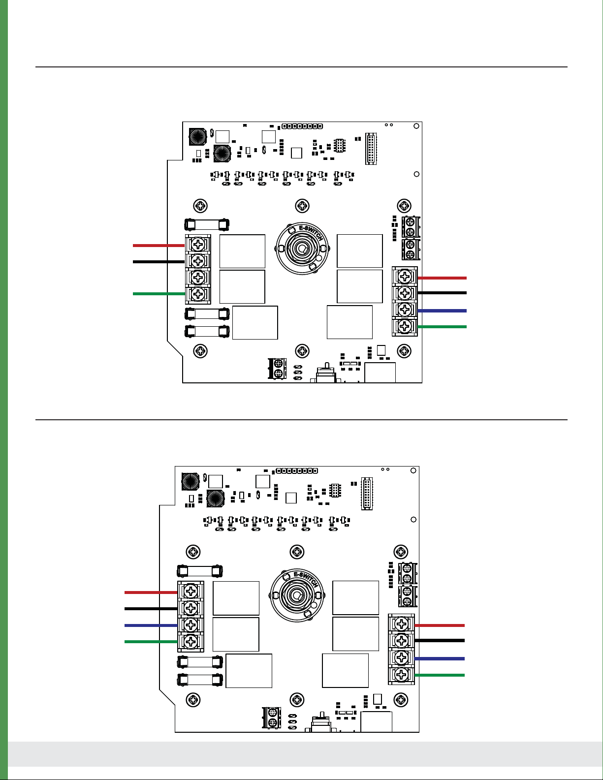
1. Manual Knob Manaully operate and disable the MX3i outputs, or set to Auto mode.
2. LED’s Indicate forward/reverse output is active.
3. Cover Screws Loosen bottom and remove top screws.
Disconnect power and remove knob (1) prior to removing cover.
4. Knockout 1/2” EMT conduit knock-outs for power in and power out to motor.
5. DC Jack Optional DC power input for backup or manual operation.
6. GrowNET™ Port RJ-45 connection for GrowNET™ digital communication.
External Features
Installation Instructions
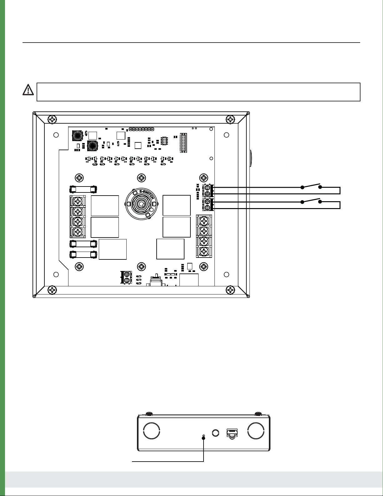
DANGER Electrocution Hazard
Disconnected all power sources before servicing or wiring. For continued protection against electric shock ensure the enclosure
is properly grounded at the marked chassis ground terminal. Install all electrical equipment and wiring in accordance with na-
tional and local electric codes. For indoor use in dry locations only (0-80% RH non-condensing.)
Replace serviceable parts only with those recommended by Agrowtek Inc.
DANGER Risque d’électrocution
Débranchez toutes les sources d’alimentation avant l’entretien ou le câblage. Pour une protection continue contre les chocs électriques assurer
l’enceinte est correctement reliée à la borne de terre du châssis marquée. Installez tous les équipements électriques et le câblage conformément
aux codes électriques nationaux et locaux. Pour une utilisation en intérieur dans des endroits secs seulement (0-80% RH sans condensation.)
Remplacer les pièces réparable seulement avec ceux recommandés par Agrowtek Inc.
4
65
4
1
2
3
Technology to Help You Grow
AGROWtEK
© Agrowtek Inc. | www.agrowtek.com
MX3i
3-Phase AC Motor Controller
U.S.A.
MADE IN
DANGER! Risk of electric shock.
Disconnect all power sources before opening cover.
Read manual before installing or operating.
Programmable Smart Relays for Automation Control
GrowNET
Link Port
modbus rtu
TM
AUTO
OFFOFF
FORWARDREVERSE

© Agrowtek Inc. | www.agrowtek.com | Technology to Help You Grow™
4
4.5”
5.5”
7.0”
6.0”
BACK
2.1”
Dimensions
Mounting holes: dia. 0.201”

© Agrowtek Inc. | www.agrowtek.com | Technology to Help You Grow™
5
Remove Cover
1. Loosen set screw on bottom of knob (1/8” at screw driver) and remove the knob.
2. Loosen bottom two cover screws 1/4”.
3. Remove top cover screws.
4. Tilt cover to clear knob shaft and lift o cover.
Mount Enclosure
1. Remove the front cover panel using caution not to damage the LED light pipes.
2. Locate the relay box and mark the mounting hole locations or use the dimensions below.
3. Pre-drill and install anchors if necessary. Keep dust and debris away from the circuit board.
Mounting hardware is not provided; drywall or deck screws of sucient length are recommended.
DO NOT drill holes into the enclosure or enlarge holes. Metal chips from drills can cause short circuits on the PCB.
4
2
3
1
DANGER! Risk of injury or death from electric shock; disconnect all power before wiring or service.
Mounting the Relay
The MX3i intelligent relay is to be securely installed to a vertical wall surface using the four mounting holes
provided in the rear of the enclosure. Removing the front cover is required to mount and wire the relay.

© Agrowtek Inc. | www.agrowtek.com | Technology to Help You Grow™
6
1. Power Input Input connections for motor power.
2. Motor Outputs Output connections for motor.
3. Motor Fuse Fuse sized according to specications. Replace only with recommended fuse.
4. DC Power Optional DC power connection for backup power.
Internal Component Locations
1
2
3
4
REPLACE FUSE
MAX 10A
L1
L2
L3
GND
GND
A
B
C
3
DC Power Connections
DC Power In
Terminal Block RJ45
GrowNET Port
DC Barrel Jack
12 - 24Vdc is required to operate the relay ’s processor and contacts which may be supplied via:
a) the GrowNET™ RJ-45 port from a GCX control system or HX8 hub,
b) the 2.1mm DC barrel jack and included power supply, or
c) the Vin terminal block on the circuit board for DIN rail power supplies.

© Agrowtek Inc. | www.agrowtek.com | Technology to Help You Grow™
7
Motor Wiring
AC power (230V) must be supplied to the relay by a branch protected circuit (circuit breaker) panel. Power
to the motor is switched by the relay to the output terminals. Limit switches on the motor should be con-
nected to the limit switch terminals on the PCB. Conduit is recommended for wiring connections.
FROM
CIRCUIT BREAKER
TO
MOTOR
REPLACE FUSE
MAX 10A
L1
L2
L3
GND
GND
A
B
C
Use 300V or higher rated multi-conductor cable for limit switch connections if run in conduit with AC conductors.

© Agrowtek Inc. | www.agrowtek.com | Technology to Help You Grow™
8
Single Phase Connection
Single phase 115-230Vac can be switched on the MX3i motor controller for single phase motors with a
forward and reverse lead. The controller will switch AC power from L1 to either A or C terminal for forward or
reverse. All motor outputs are o when the motor controller is stopped.
REPLACE FUSE
MAX 10A
L1
L2
L3
GND
GND
A
B
C
L1
L2/NEUTRAL
GROUND
FORWARD
L2/NEUTRAL
REVERSE
GROUND
AC INPUT:
TO MOTOR:
REPLACE FUSE
MAX 10A
L1
L2
L3
GND
GND
A
B
C
L1
L2
GROUND
PHASE A
PHASE B
PHASE C
GROUND
L3
AC INPUT:
TO MOTOR:
Three Phase Connection
Three phase 230Vac can be switched on the MX3i motor controller. The controller will swap phases A and C
to reverse the motor. All phases are o when the motor controller is stopped.

© Agrowtek Inc. | www.agrowtek.com | Technology to Help You Grow™
9
Motors must be wired to include the limit switches in the motor to terminate operation and prevent damage
to a structure in the event the motors are over-run.
Limit Switch Wiring
REPLACE FUSE
MAX 10A
L1
L2
L3
GND
GND
A
B
C
Reverse Limit
Forward Limit
Vdc
Limit switch inputs operate using the DC input voltage (12-24Vdc) supplied to the switch and returned to
the input terminal.
Limit Switch Defaults
Limit switches are expected to be Normally Closed in the normal range of operation and Open when the
limit is met. The MX3 can be congured to operate in the opposite manner with the limit switches in the
Normally Open position during normal operation and Closed when the limit is met.
Invert Limit Switch Inputs
To‘invert’the limit switches to “normally open”type (limit when closed) press the reset button momentarilly.
The limit switches will now work in the opposite manner.
The MX3 will not operate the motor relays unless the limit switches are properly connected or terminals jumpered
unless the inputs are inverted as described below.
Reset Button

© Agrowtek Inc. | www.agrowtek.com | Technology to Help You Grow™
10
GrowNET™ Hubs
All GrowNET™ devices are connected using standard CAT5 Ethernet cable with RJ-45 connections.
Devices can be connected directly to the GrowNET™ ports on the bottom of the controller, or through HX8
GrowNET™ hubs. It is typical to simplify cabling by locating hubs centrally in hall ways and rooms allowing
single runs from an 8-port device hub back to a central hub or back to the controller.
HX8 GrowNET ™ hubs expand a single port into eight more ports.
Hubs can be daisy-chained to form a network of up to 100 devices per
GrowNET™ bus. Individually buered port transcievers provide excellent
signal integrity and extended communication strength and range.
Hubs provide up to 1A of power for operating sensors and most relays
directly over the CAT5 cable. A DC jack on the hub provides 24Vdc power
to the ports from the included wall power supply. A terminal block
power option is also available.
DIELECTRIC GREASE
Dielectric grease is recommended on RJ-45 GrowNET™ connections when used in humid environments.
Place a small amount of grease onto the RJ-45 plug contacts before inserting into the GrowNET™ port.
Non-conductive grease is designed to prevent corrosion from moisture in electrical connectors.
• Loctite LB 8423 • Dupont Molykote 4/5 • CRC 05105 Di-Electric Grease
• Super Lube 91016 Silicone Dielectric Grease • Other Silicone or Lithium based insulating grease
NOTICE
GrowNET™ ports use standard RJ-45 connections but are NOT compatible the Ethernet network equipment.
Do not connect GrowNET™ ports to Ethernet ports or network switch gear.
Installation Notes
Refer to the GCX controller manual for details on adding the device to the system.
Connection to GrowControl™ GCX
Table des matières
Autres manuels Agrowtek Contrôleurs


