AGA Rangemaster Rayburn Ranger Guide de démarrage rapide

Rayburn Ranger
Field Service Manual
The information detailed in this guide applies to the Rayburn Ranger electric cooker, at all times the
service technician MUST apply their competencies and ensure the appliance is left safe for continued
use, should the appliance fail any test then engineering judgement must be applied as to whether
the appliance can be left operational.

Contents
Product Overview. ..................................................................................................................................3
General information ...............................................................................................................................3
Cooking zones .........................................................................................................................................4
User control panel...................................................................................................................................5
Roasting Oven and Grill.......................................................................................................................5
Baking/Simmering Oven .....................................................................................................................5
Warming Oven....................................................................................................................................5
Removal and replacement of top plate element and Induction unit.....................................................9
Removal and replacement of Induction unit........................................................................................10
Removal and replacement of side panels.............................................................................................11
Roast oven base and grill element removal,.........................................................................................13
Roast oven base element removal and replacement...........................................................................14
To gain access and remove and replace the warming oven element...................................................15
Access to the grill cooling fan. ..............................................................................................................16
Bottom left oven overheat thermostat. ...............................................................................................16
To gain access to the main terminal block, switches and thermostats................................................17
Switch and Thermostat Identification ..................................................................................................17
Removal and replacement of lid liner...................................................................................................18
Removal and replacement of lid top ....................................................................................................19
Removal and replacement of front plate. ............................................................................................21
Removal and replacement of front plate. ............................................................................................22
Essential Parts.......................................................................................................................................23
Circuit diagram. Rayburn Ranger..........................................................................................................24

Page 3of 25
Product Overview.
The brand new Rayburn Ranger, a fully-electric Rayburn cooker providing flexible, energy-efficient
cooking and stunning styling.
A cast iron hotplate that can be set to boiling or simmering mode.
Two zone Induction hob.
The cooker includes two large capacity radiant ovens plus a warming oven, which operate
independently. It also benefits from a grill,
The Rayburn Ranger vents into the room. We recommend this model is used in conjunction with a
cooker hood. The oven vent outlets are located on top of the Ranger and are designed for venting
the moisture from the ovens.
General information
Regular servicing is not required for this cooker
DO NOT ALTER or MODIFY the appliance.
The appliance warranty does not cover commercial use.
Please refer to the Rayburn Ranger cooker installation instructions for specific information
regarding appliance dimensions, clearances, electrical requirements etc.
Installation instructions and are available to view at
https://www.agaliving.com/sites/default/files/user_guides_uploaded/07-
22%20EINS%20517932%20RAYBURN%20RANGER%20100%20i%20GB_1.pdf
*Important Note*
Before carrying out work on the appliance, the power supply MUST be isolated and tested for safe
electrical isolation.
All electric 2 x 13 amp connections.
The main cooker and the induction unit assembly are electrically tested before leaving the factory.
Always inspect the cooker before any work is carried out and notify the customer of any existing
damage.

Page 4of 25
Cooking zones

Page 5of 25
User control panel.
The Ovens
Roasting Oven and Grill
The upper oven is indirectly heated by two elements, one concealed in the base of the oven and the
other is visible in the roof. These elements heat the lined cavity to provide cooking results consistent
with traditional heat storage ovens, but with the flexibility to turn the ovens off when not in use. The
appliance features three settings Roast, Grill & Bake
Baking/Simmering Oven
The lower oven is indirectly heated by two elements, one concealed in the base and the other visible
in the top of the oven. These elements heat the lined cavity oven to provide cooking results
comparable with traditional heat storage ovens, but with flexibility to turn the oven off when not in
use. The appliance features two settings bake and simmer.
Warming Oven
The Warming oven is indirectly heated by one element which is fitted underneath the oven.
The OVEN IS NOT A HOLDING OVEN and therefore is not designed to hold food at a given
temperature for long periods

Page 6of 25
Essential tools
Always protect the cooker and work area before carrying out any work on the appliance.
Inspect the cooker for any existing damage before starting work.
When undertaking maintenance work on this appliance the engineer should ensure the following
tools are available
Multi meter
Clamp meter
Insulation resistance tester
Tool kit
Torque driver with screwdriver bits
The main electrical terminal block connections on the Rayburn Ranger must be tightened by the use
of a torque screwdriver, please see below for the correct setting.
Main Terminal Block connections 2.5Nm.
Page 7of 25
Removal and replacement of major components
Before carrying out work on the appliance, the power supply MUST be isolated
and tested for safe electrical isolation.
The Rayburn Ranger utilises a wheel system which allows the appliance to be wheeled out from its
position for essential work to be carried out.
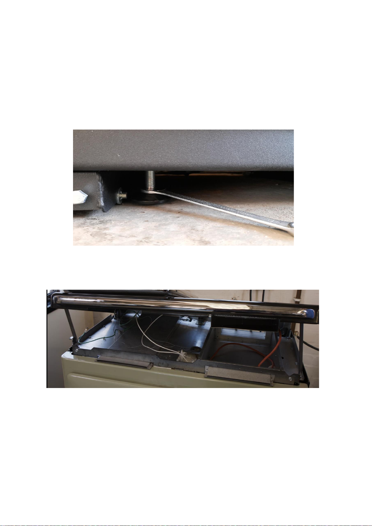
When removing the cooker from its position, the front stability feet can be raised with a 13mm
spanner to allow the cooker to be wheeled out from its position.
To gain access to the front stability feet remove the front plinth at the base of the cooker.
Some repairs will require the top plate to be lifted it is recommended to utilise two engineers for
this , the top can be propped ( as shown ) or alternatively one engineer can hold the top upright
while the other engineer carries out the work.

Page 8of 25
To gain access to the underside of the top plate.
To lift the top plate, remove 4 chrome caps covering the corner stay nuts, then remove the 4 corner
stay nuts Fig1.
The top plate can then be lifted upwards from the main chassis,
You can then view the underside of the top plate along with the fitting of the element and the
induction unit.
Fig1. Chrome caps and corner stay nuts x 4

Page 9of 25
Removal and replacement of top plate element and Induction
unit.
To remove the hob element, follow the element leads and unplug the electrical connection plug,
remove the hob element retaining bar on the underside of the element, loosen the 2 screws
securing the thermostat phial to the underside of the element and withdraw the thermostat phial
from the element, the element can then be lifted out of position
.
Replace in reverse order, always remember to refit the earth connection.
Element plug –in connection
Element retaining bar.
Thermostat phial bracket

Page 10 of 25
Removal and replacement of Induction unit.
To remove / replace the induction unit the top plate will need to be lifted and supported, disconnect
the plug –in electrical connection Fig2, then remove induction cover plate and the cable brackets
Fig3.
Fig 2 Fig 3
When the induction unit cover plate is removed this will allow access to the mounting brackets Fig 4
,remove the 4 screws and then carefully remove the springs securing the unit , then gently pull the
induction unit off the brackets Fig 5 and replace in reverse order.
Fig 4. Fig 5.
Table des matières


