AEG ARE I2 Manuel utilisateur

Manual
Compact Reader ARE I2
Installation Guide
for Systems with a
Serial Interface (RS 232)

Manual
Page 2 / 33- Revision 01
ARE I2 / RS 232 – Installation Guide
AEG
Identifikationssysteme GmbH
Söflinger Straße 100
D-89077 Ulm
Tel. ++49(0)731-933-1340/1877
Fax ++49(0)731-933-1855
e-mail: [email protected]
Contents
1 INTRODUCTION 5
2 SYSTEM OVERVIEW 5
3 START-UP PROCEDURE 6
4 INSTALLATION 7
4.1 Mounting of the Housing 7
4.2 Grounding of the Reader 7
4.3 Assemblage of the Line Connectors 7
4.3.1 Allowed Diameter of the Used Cables 8
4.3.2 Assembling of the Cable Pipe 8
4.3.3 Mounting of the Power Supply Cable 9
Assembling of the Power Supply and Data Cable (Single Cable Pipe) 10
4.3.5 Final Assembly of the Cable Pipe 11
4.3.6 Plug in of the SAB Cab 11
4.3.7 Using the Service Cable ID 70213 12
4.3.8 Using the Power Supply and Data Cable ID 70212 13
4.4 Power Supply 13
5 VISUAL SIGNAL LAMPS 14
6 SETTINGS OF THE READER / MOST IMPORTANT PARAMETERS 15
6.1 General 15
6.2 Error Codes 16
6.3 CID – Suppression of ID Codes 16
6.4 CN – Suppression of No Reads 17
6.5 NID- Failure Protection 17
6.6 EC- Echo 19

Manual
Page 3 / 33- Revision 01
ARE I2 / RS 232 – Installation Guide
AEG
Identifikationssysteme GmbH
Söflinger Straße 100
D-89077 Ulm
Tel. ++49(0)731-933-1340/1877
Fax ++49(0)731-933-1855
e-mail: [email protected]
6.7 BD- Baudrate 19
6.8 TOR – Maximum Reading Time 20
6.9 VS- Show Parameter 20
6.10 VSAVE – Save Parameter 20
7 OPERATING MODES OF THE READER 21
7.1 Mode 2 – Triggered by an Software Command 21
7.1.1 Settings of the Reader / Most Used Parameters 22
7.1.2 Basic Data Exchange Process 23
7.1.3 ReadOnly-Transponder 23
7.1.4 R / W –Transponder 23
7.1.4.1 Standard Read Process / Serial Number of the Transponder GT 23
7.1.4.2 Selective Read RD 24
7.1.4.3 Writing Process WD 24
7.2 Operating Mode 0 - Continuous Reading 26
7.2.1 Settings of the Reader / Most Used Parameters 26
8 INSTRUCTIONS 28
8.1 General Instructions 28
8.2 Special Instructions for Using a Read / Write System 29
9 HOTLINE 30
10 REFERENCE DOCUMENTATION 30
11 REVISIONS 30
12 APPENDIX 31
12.1 Best Orientation for an F-Type -Reader 31
12.2 Best Orientation for an L-Type -Reader 32
12.3 Assembling of the SAB Cab 33

Manual
Page 4 / 33- Revision 01
ARE I2 / RS 232 – Installation Guide
AEG
Identifikationssysteme GmbH
Söflinger Straße 100
D-89077 Ulm
Tel. ++49(0)731-933-1340/1877
Fax ++49(0)731-933-1855
e-mail: [email protected]

Manual
Page 5 / 33- Revision 01
ARE I2 / RS 232 – Installation Guide
AEG
Identifikationssysteme GmbH
Söflinger Straße 100
D-89077 Ulm
Tel. ++49(0)731-933-1340/1877
Fax ++49(0)731-933-1855
e-mail: [email protected]
1Introduction
This document will describe the components of the Compact Reader System ARE I2 / RS 232
and the procedure how to do the first set up of the reader.
The main features of the reader are listed below:
•the antenna is placed inside of the housing (base version)
•there are algorithm available to read nearly all 125 kHz-transponders on market
•the serial RS 232-Interface is placed inside of the housing, allowed baud rate are up to
19200 Bit/s
•the allowed supply voltage is 9 to 30VDC
•low power consumption of reader < 1.2 Watt
•high reliability for reading and writing within an industrial environment.
•compact housing of the reader with multiple ways for mounting.
•the cabling concept of the reader is optimised to service demands.
•the protection class of the housing is IP65
•there is a set of external antennas available to meet special application demands ( X-tended
version)
2System Overview
In the base version all electronic components of the reader is placed inside of a small plastic
housing.
Figure 2-1: Concept of the Reading System
RS232
(9-Pin SubD)
Transponder
Reader with
Integrated Antenna
ARE I2
24V
DC

Manual
Page 6 / 33- Revision 01
ARE I2 / RS 232 – Installation Guide
AEG
Identifikationssysteme GmbH
Söflinger Straße 100
D-89077 Ulm
Tel. ++49(0)731-933-1340/1877
Fax ++49(0)731-933-1855
e-mail: [email protected]
The connection of the cables (power supply and data transfer) is done inside of the connection
cab (SAB Cab). Together with an sealing element a protection classification of IP 65 is guar-
anteed.
By means of the integrated antenna the reader generates an alternating magnetic field, which
powers the transponder. Coded signals sent back from the transponder are received and de-
coded by the reader
The reader is fully controlled by an Master with RS 232 data port, while using the integrated
serial RS 232 Interface of the reader.
The side of the housing showing the antenna symbol must not be brought next to a metal sur-
face. This could lead to a significant change of the properties of the antenna circuit, which in
turn reduces the reading range considerably.
Environmental electromagnetic noise may also reduce the specified reading performance.
Special hints to overcome these problems are documented in Chapter 8.
3Start-up Procedure
The start-up procedure of the reader system is split up to following steps:
•mounting of the reader and pin connection (cabling), see Chapter 4
•operational instructions, see Chapter 7
To get a feeling how the IdentSystem will work, first start the reader controlled by the se-
rial interface (RS 232) of an isolated PC.
The next step is to integrate the reader to the operating network.

Manual
Page 7 / 33- Revision 01
ARE I2 / RS 232 – Installation Guide
AEG
Identifikationssysteme GmbH
Söflinger Straße 100
D-89077 Ulm
Tel. ++49(0)731-933-1340/1877
Fax ++49(0)731-933-1855
e-mail: [email protected]
4Installation
To get the specified reading performance it is necessary to do the installation carefully step by
step as it is described in the following Chapters. All the work must be done by well educated
people.
4.1 Mounting of the Housing
The reader can be mounted to any other mechanic construction. It is recommended to protect
the housing against heavy mechanical interactions.
Attention!
The side of the housing showing the antenna symbol must not be brought next to a metal
surface. This could lead to a significant change of the properties of the antenna circuit,
which in turn reduces the reading range considerably.
With the help of the plastic bars, the reader can mounted or screwed on to the most fastening
elements without open the housing of the device.
4.2 Grounding of the Reader
To get reliable reading results, the reader must be grounded. The connector is place at the side
of the housing (6.35 mm flat contact).
To avoid EMV-problems, the cable to ground ought to be very short with low impedance.
Attention! The topology of the ground wires must be done in the right way (according state of
art).
4.3 Assemblage of the Line Connectors
The connection of the power supply and data transfer cables are done by using the connectors
of the SAB Cab. The Assemblage inside of the SAB Cab is described in Chapter 4.3.1 to
4.3.7.
Manual
Page 8 / 33- Revision 01
ARE I2 / RS 232 – Installation Guide
AEG
Identifikationssysteme GmbH
Söflinger Straße 100
D-89077 Ulm
Tel. ++49(0)731-933-1340/1877
Fax ++49(0)731-933-1855
e-mail: [email protected]
Inside of the SAB Cap there are the pins of following connections:
•power supply
•data link to the serial interface RS232
The codes to order the SAB Cabs and preassembled cables are listed below:
ID 70212 SAB-Cab incl. one PG9 cable pipe and 5 wire cable (standard cable)
ID 70213 SAB-Cab incl. one PG9 cable pipe and 5 wire cable / Sub D 9 Connector
(Service Cable)
ID 70221 SAB-Cab incl. one PG9 cable pipe
ID 70215 SAB-Cab incl. two PG9 cable pipes
ID 70219 SAB Cab without any cable pipe. The cabling is done by the customer himself.
4.3.1 Allowed Diameter of the Used Cables
The allowed diameters of the cables used for data link and power supply must be in the range
from ∅3,5 to ∅8mm. For this case, IP 65 is reached.
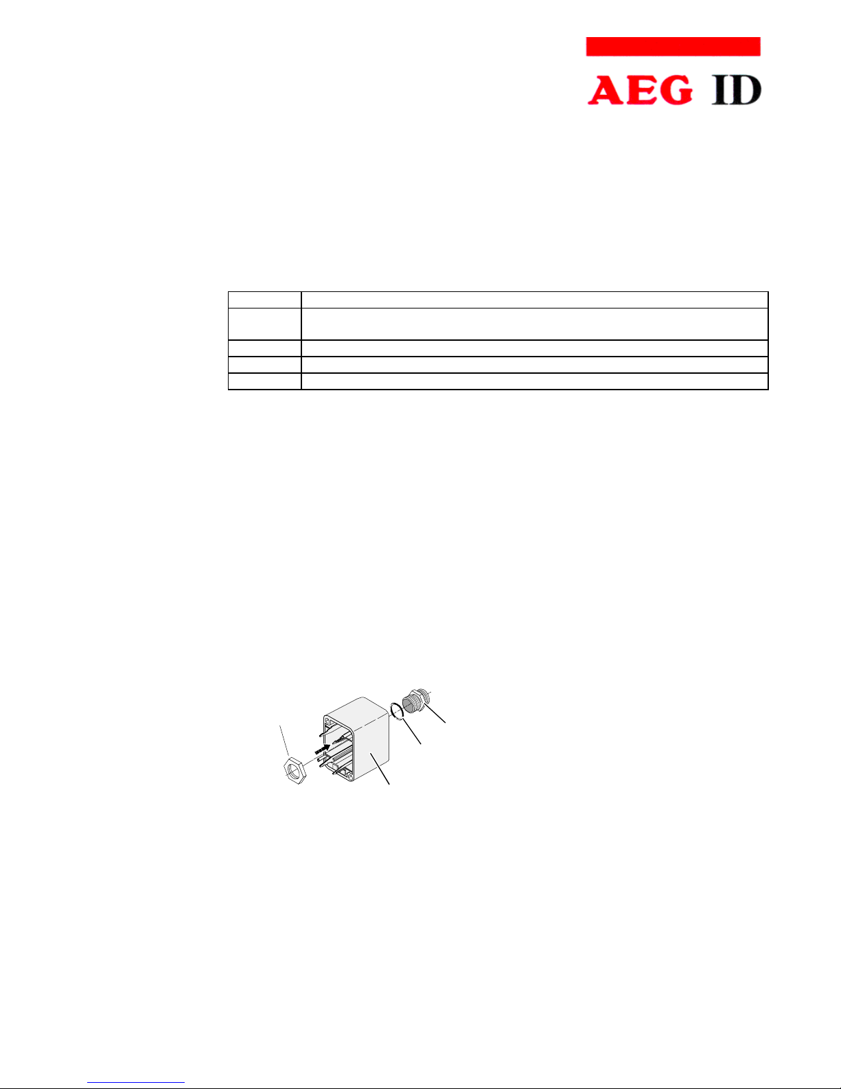
4.3.2 Assembling of the Cable Pipe
If no preassembled SAB Cab are used (Best-Nr. ID 70214), the assembling must be done in
following way:
•Breakthrough the prepared areas at the surface of the SAB Cabs. There are two prepared
areas seen at the SAB Cab: central and at one side of the cab.
•The sealing must be done in the correct way O-Ring (3) at the cable pipe (4) (see also
Figure 4-1.
1
2
3
4
Figure 4-1:Assembling oft the Cable Pipe
•Bring the nut (2) of the cable pipe inside of the SAB Cab (1).
•To fasten the nut please use the right tool (17mm)..

Manual
Page 9 / 33- Revision 01
ARE I2 / RS 232 – Installation Guide
AEG
Identifikationssysteme GmbH
Söflinger Straße 100
D-89077 Ulm
Tel. ++49(0)731-933-1340/1877
Fax ++49(0)731-933-1855
e-mail: [email protected]
3
4
5
1
6
Cable
7
4.3.3 Mounting of the Power Supply Cable
The power supply cable must be mounted in following steps:
•Remove all inner parts from the cable pipe at the SAB Cab (1) ( nut (5), pipe(4) and cable
fastener (3)) (see Figure 4-2)
•Put all the removed parts ( nut (5), pipe (4), cable fastener (3)) and the cable pipe of the
SAB Cab as well (1 to 4) to the cable.
Figure 4-2: Arranged Parts for Mounting
•Remove the outer isolation of the cable at a length of 6cm .
•Remove the isolation of the wires at a length of 6 [mm] and stick a covering hull to the litz
wire.
•Put the cable to the cable pipe. The length of the cable coming out the SAB Cab must long
enough to do all further installation steps in an easy way.
•Stick the pipe (4) into the cable fastener (3).
•Stick the cable fastener (3) into the cable pipe.
•Connect the power supply cable into the right places of the MINI-COMBICON-Connector
(see Figure 4-2 Part (6)).
•The pin assignment is shown in the figure below.

Manual
Page 10 / 33- Revision 01
ARE I2 / RS 232 – Installation Guide
AEG
Identifikationssysteme GmbH
Söflinger Straße 100
D-89077 Ulm
Tel. ++49(0)731-933-1340/1877
Fax ++49(0)731-933-1855
e-mail: [email protected]
4.3.4 Assembling of the Power Supply and Data Cable (Single Cable Pipe)
The connection of the cable is also done inside of the SAB Cab. Instead of an 2-wire power
supply cable there is now an 5-wire data cable needed. The diameter of the inner wires must
be big enough to keep the voltage drop in the specified range.
The steps to mount the cable is decried in Chapter 4.3.3.
B
A
D
C
E
green
-
+
L
+U
S
-U
S
U
L
black
shielding
NC
shielding
+9..30V
DC
GND (0V)
TXD
RXD
NC
ARE I2
V+
DC
TxD (reader)
GND
RxD (reader)
V+
DC
B
A
C
D
E
green
-
+
L
+U
S
-U
S
U
L
black
NC
shielding
+9..30V
DC
GND (0V)
TXD
RXD
NC
ARE I2
Table des matières
Autres manuels AEG Lecteur de cartes


