ENGLISH
B-TWIG 8 MOBILE | User manual
6
7
User manual | B-TWIG 8 MOBILE
life cycle. In order to preserve battery duration
and reliability over time, avoid battery complete
discharge during operation.
13 STATUS
Pressfor3secondsthis buttontoviewthecharge
status of the internal battery. Reporting occurs
when the system is off (OFF) or when the unit is
connected to the mains with the POWER switch
in the CHARGE position.
14 DIGITAL MATRIX CONTROLLER
LCDcontrolinterfaceanddigitalmenudisplay;for
details see chapter 5 SYSTEM CONTROL.
15 SETUP/MAIN LEVEL
Thisrotaryknobwithintegratedpushbuttonisthe
primary controller of system digital functions. It
allowsaccesstothecontrolmenuandadjustment
of the parameters selected according to the
connected devices or application preferences.
It also acts as a classic MAIN LEVEL knob for
adjusting the overall system output volume.
16 SIG/CLIP
Two-color output level indicator
Green LED: the signal is present
Red LED: the signal is very strong and is close
to distortion.
IftheredLEDlightsupcontinuously,itisnecessary
to reduce the MAIN LEVEL level or, otherwise,
adjust the levels/parameters of CH1, CH2, CH3.
7 STEREO AUX IN
Unbalanced input with 3.5mm mini-jack stereo socket.
Connecttothisinputthesignalfromanexternaldevicesuch
as Smartphone, Tablet or PC. It is possible touse this input
and the Bluetooth®signal at the same time, but for better
levels management, we do not recommend this option.
8 CHANNEL 3 LEVEL
Thiscontroladjustschannel3level.Turntheknobclockwise
to increase the volume or counterclockwise to decrease it.
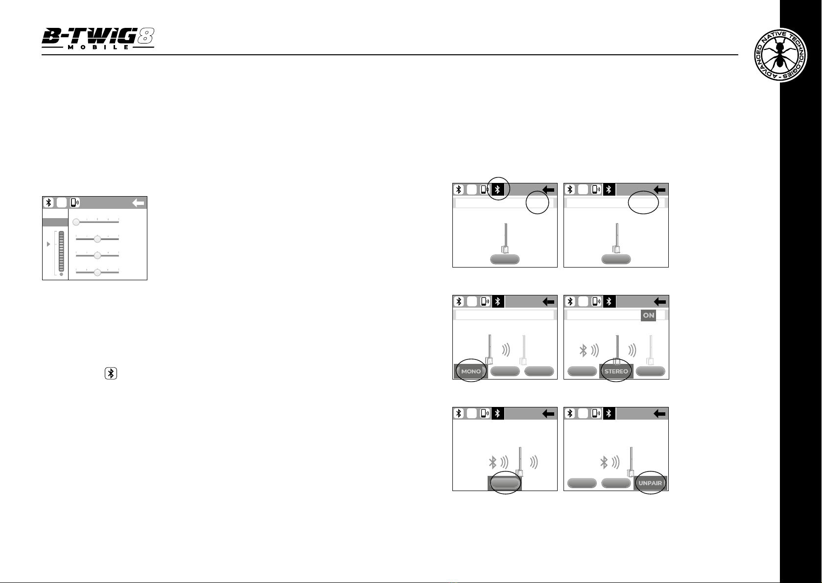
9 LED PAIRING
Status LED for Bluetooth®connection:
- Flashing green light, synchronization and pairing with
the mobile device.
- Steady green light, audio streaming in progress.
Tosynchronizeandconnect mobilephonesor tablets,refer
to chapter 5 SYSTEM CONTROL.
10 MAIN OUT CONNECTOR
BalancedXLR-Moutputforconnectiontoanotherpowered
system. The signal of this output depends on the levels of
the input channels. Using the APP menu the output can
be set as LINK OUT or MIX OUT.
11 BATTERY LEVEL
Internal battery status LEDs, in descending order
1st LED: steady green light, battery fully charged
2nd LED: steady green light, battery half charged
3rd LED: steady green light, battery one quarter charged
4th LED: steady red light, battery close to discharging,
recharge the battery as soon as possible.
12 CHARGE LED
While the internal battery is charging, this LED is lit.
When the battery is fully charged, the process stops
automatically and the CHARGE LED turns off.
In order to charge the battery, it is necessary to connect
the power cable to the wall socket and place the POWER
button in CHARGE mode. Battery total charge is achieved
in about 5 hours.
It is also possible to recharge the battery less effectively,
even during system operation connecting the unit to the
mains and moving the POWER button to ON position.
WARNING:Lithium-ionbatteries,iffullydischargedtozero,
can suffer irreparable damage that abruptly shortens their
14
16
15
10
12 13
8
11
7 9