Advanced Instruments OsmoTECH PRO Manuel utilisateur

Hot-Line Technical Service: Advanced Instruments and worldwide distributor network provides 24/7
comprehensive customer service and technical support.
©2019 Advanced Instruments. Alltrademarks are the property of their respective companies.
Two Technology Way / 781-320-9000
Norwood, Massachusetts 02062, USA
800-225-4034 Fax:781-320-8181
aicompanies.com
222104PM Rev 0
Replacement Procedure 222104PM
OsmoTECH®PRO Sample Probe
Motor
Scope
This document describes how to replace the sample
probe motor (p/n 222104R) on the OsmoTECH® PRO
Multi‑Sample Micro‑Osmometer. It is intended for use in
conjunction with service procedures that require access
to the OsmoTECH PRO interior.
Tools required
• #1 and #2 Phillips screwdrivers
• 1/4“ and 5/16” nut driver
• 0.050”, 3/32”, and 9/64” Allen wrenches
• 30 µL sample tube
• Static grounding wrist strap
Parts and materials required
Replacement part 222104R
Related documents
• OsmoTECH PRO Disassembly and Reassembly
(p/n 222202PM)
• OsmoTECH PRO Service Guide (p/n 222006EN)
Safety notices
WARNING: Hazardous Voltage. Power cord must
be disconnected to prevent electrical shock.
NOTICE: Internal components may be damaged
by static electricity. A static grounding wrist
strap must be worn during this procedure.
NOTICE: Improper connections may cause
damage to the instrument.
Disconnecting the control PCB
1. Disassemble the instrument by performing the
disassembly instructions in OsmoTECH PRO
Disassembly and Reassembly.
2. Remove the cable clamp [A] that secures the C10
sample probe cable and the C11 block probe cable
to the side of the power supply and controls
assembly.
A
3. Unplug the C10 and C11 connectors from the control
PCB.
4. Unplug the B1, B2, B3, B4, B6, B7, B8, B9, and B10
connectors on the motor/sensor cable harness from
their mating connectors.
5. Disconnect the A1, A2, A3, and A4 connectors on
the cooling system harness from their mating
connectors.
Replacement Procedure
OsmoTECH® PRO Sample Probe Motor
Page 2 222104PM Rev 0
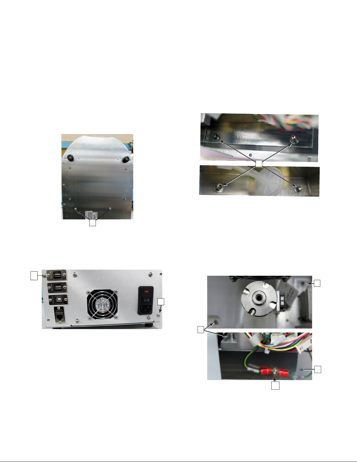
Removing the power supply and controls
assembly
1. Rest the instrument on its back side.
2. Remove the two screws [B] that secure the power
supply and controls assembly to the bottom of the
chassis.
B
3. Place the instrument in the upright position.
4. Remove the two screws that secure the power
supply and controls assembly to the rear of the
chassis.
C
C
5. Slide the power supply and controls assembly out
of the base assembly.
Removing the osmometer module
1. Remove the four socket head cap screws and
washers [D] that mount the osmometer module
mounting bracket to the chassis.
D
2. Carefully slide the module out of the instrument.
3. Remove the hex nut and washer [E] that secures
the SPG and BPG ring terminals to the side of the
osmometer module mounting bracket.
4. Remove the four socket head cap screws and
washers [F] that mount the osmometer module to
the osmometer module mounting bracket (which
is secured to the chassis).
F
F
F
E
5. Lift the osmometer module o of the osmometer
module mounting bracket.

Replacement Procedure
OsmoTECH® PRO Sample Probe Motor
Page 3 222104PM Rev 0
Removing the sample probe motor
1. Remove the sample probe motor’s wire leads from
the two cable clamps [E] and the three cable clips
[F].
F
E
2. Remove the hex nut and washer [G] that secure the
sample probe motor’s lead‑screw to the top of the
osmometer module top plate.
G
3. Hold the movable plate that secures the body of the
sample probe motor and remove the set‑screw [H]
from each side of the osmometer module top plate.
Keep hold of the movable plate once the set‑screws
are removed to prevent the plate from dropping.
H
4. Gently lower the movable plate until it rests on top
of the stripper bracket.
5. Remove the two socket head cap screws [I] and
washers that mount the sample probe motor to the
movable plate.
I
Replacing the sample probe motor
Refer to Removing the sample probe motor for images
and callouts.
1. Secure the replacement sample probe motor to the
movable plate using the two socket head cap
screws and washers [I].
2. Lift the movable plate until the adapter on the end
of the sample probe motor’s lead‑screw enters the
osmometer module top plate and the adapter’s
threads are extending beyond the top of the plate.
3. Secure—but do not fully tighten—the adapter
threads with the hex nut and washers [G].
4. Partially thread the two set‑screws [H] into the
sides of the osmometer module top plate.
5. Lift the movable plate that secures the sample
probe motor until the lead‑screw’s adapter is
properly positioned inside the osmometer module
top plate.
6. Hold the movable plate and tighten the two set‑
screws [H].
7. Tighten the hex nut to secure the adapter’s threads
[G].
If the sample probe motor’s lead‑screw turns as the
nut is being tightened, then the two sets‑screws are
not tight enough.

Replacement Procedure
OsmoTECH® PRO Sample Probe Motor
Page 4 222104PM Rev 0
8. Lift and lower the movable plate several times to
make sure that there is no binding, etc.
9. Secure the sample probe motor’s wire leads with
the two cable clamps [E] and the three cable clips
[F].
Make sure that there is a service loop [L] between
the body of the motor and the first cable clamp.
L
Replacing the osmometer module
Refer to Removing the osmometer module for images
and callouts.
1. Slide the osmometer module into the instrument.
2. Secure the osmometer module to the mounting
bracket using the four socket head cap screws and
washers [D].
Replacing the power supply and controls
assembly
Refer to Removing the power supply and controls
assembly for images and callouts.
1. Slide the power supply and controls assembly into
the base assembly.
2. Secure the power supply and controls assembly to
the rear of the chassis with the two screws [C].
3. Place the instrument on its back side.
4. Secure the power supply and controls assembly to
the bottom of the chassis with the two screws [B].
Reconnecting the control PCB
1. Place the instrument in an upright position.
2. Plug the A1, A2, A3, and A4 connectors on the
cooling system harness into their mating
connectors.
3. Plug the B1, B2, B3, B4, B6, B7, B8, B9, and B10
connectors on the motor/sensor cable harness into
their mating connectors.
4. Plug the C10 and C11 connectors into the control
PCB.
5. Secure the C10 sample probe cable and the C11
block probe cable to the side of the power supply
and controls assembly with the cable clamp and
screw [A].
6. Reassemble the instrument by performing the
reassembly instructions in OsmoTECH PRO
Disassembly and Reassembly.
Autres manuels pour OsmoTECH PRO
3


