Advanced Energy iLS600 Series Manuel utilisateur
©2021 Advanced Energy Industries, Inc.
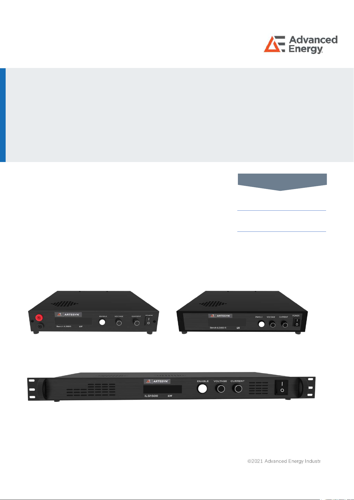
Advanced Energy’s Artesyn iLS600, iLS600-R and iLS1500
series are programmable DC power supplies with a single
output that offers output power to 600 and 1500 watts. With
12-bit D/A & A/D converters embedded, the power supplies
come with the capability of reporting voltage and current very
accurately. The iLS600, iLS600-R and iLS1500 series provide
convenient digital rotary controls for voltage and current
adjustment and the power supplies also come with rear ports
that allow remote control via USB, Ethernet, and analog
control inputs. The iLS600, iLS600-R and iLS1500 series are
LXI certified.
ARTESYN
iLS600, iLS600-R and iLS1500 Series
Intelligent Laboratory Power
600W/1500W Programming Manual
AT A GLANCE
Total Power
600 and 1500 Watts
# of Outputs
Single
USER MANUAL

iLS600, iLS600-R and iLS1500 Series
Rev. 05.20.21_#1.0 advancedenergy.com 2
SECTION DESCRIPTION PAGE
1 OPERTATING MODES 5
1.0 Bench iLSOperating Modes 5
1.0.1 Local 5
1.0.2 Remote 5
1.0.3 Remote with Lock 5
1.0.4 Analog Voltage Control 5
1.0.5 Analog Current Control 5
1.0.6 Analog Dual Control 6
1.0.7 Parallel Mode 6
1.0.8 Series Mode 6
1.0.9 Mode Transitions Commanded from Front Panel 6
1.0.10 Mode Transitions Commanded via Remote SCPI Command 7
1.1 Local Mode 8
1.2 Remote Mode 9
1.2.1 SCPI Commands 9
1.2.2 Front Panel Commands 9
1.2.3 Additional Capabilities 10
1.3 Remote with Lock Mode 10
1.4 Analog Voltage Control Mode 10
1.4.1 Voltage Setpoint 10
1.4.2 Current Setpoint 11
1.4.3 Activating/Deactivating the Output 11
1.4.4 Remote Queries 11
1.4.5 Additional SCPI Commands 11
1.4.6 Additional Capabilities 11
1.5 Analog Current Control Mode 12
1.5.1 Voltage Setpoint 12
1.5.2 Current Setpoint 12
1.5.3 Activating/Deactivating the Output 12
TABLE OF CONTENTS

iLS600, iLS600-R and iLS1500 Series
Rev. 05.20.21_#1.0 advancedenergy.com 3
SECTION DESCRIPTION PAGE
1.5.4 Remote Queries 12
1.5.5 Additional SCPI Commands 13
1.5.6 Additional Capabilities 13
1.6 Analog Dual Control Mode 13
1.6.1 Voltage Setpoint 13
1.6.2 Current Setpoint 14
1.6.3 Activating/Deactivating the Output 14
1.6.4 Remote Queries 14
1.6.5 Additional SCPI Commands 15
1.6.6 Additional Capabilities 15
2 REMOTE SENSE CONFIGURATION 16
2.0 Enable/Disable BENCH iLS Remote Sense 16
2.1 Calculate the Lead Resistance 16
3 CALIBRATION 17
3.0 Calibration Sequence 17
4 SELF-TEST 19
5 MISCELLANEOUS COMMANDS 20
5.0 *CLS 20
5.1 *IDN? 20
5.2 *RST 20
5.3 SYSTem:PROMpt<ON|OFF> 20
6 STATUS AND ERRORS 21
6.0 Architecture 21
6.0.1 Over-Voltage Error 22
6.0.2 Over-Current Error 22
6.0.3 Over-Power Error 22
6.0.4 Not Calibrated 22
6.0.5 Watchdog Error 23
6.0.6 Self-Test Error 23
6.0.7 Output Error 23
TABLE OF CONTENTS

iLS600, iLS600-R and iLS1500 Series
Rev. 05.20.21_#1.0 advancedenergy.com 4
SECTION DESCRIPTION PAGE
6.0.8 SCPI Access 23
6.0.9 Questionable Status Fan-Out Registers 23
6.0.10 Temperature Status Register 24
6.0.11 Hardware Status Register 25
6.0.12 Operation Status Register 26
6.0.13 Standard Event Status Register 28
6.0.14 Error/Event Queue 29
6.0.15 Error Condition Register 31
6.0.16 Status Byte Register and Service Request Enable Register 32
7 DRIVERS 34
7.0 USB Driver 34
7.1 IVI Drivers 38
7.2 LabView Drivers 39
APPENDIX 40
SCPI Commands 40
TABLE OF CONTENTS

iLS600, iLS600-R and iLS1500 Series
Rev. 05.20.21_#1.0 advancedenergy.com 5
1.0 Bench iLSOperating Modes
1.0.1 Local
In Local mode, the user controls BENCH iLS via the front panel. While in Local mode the
user can achieve nearly full capability via the SCPI command interface, EXCEPT for setting
operational voltage and current setpoints and activating the output. The SCPI command to
deactivate the output will be executed. While in Local mode, the Analog Voltage and Analog
Current inputs are ignored.
1.0.2 Remote
In Remote mode, full capability is available over the SCPI command interface. The front
panel Voltage and Current control knobs are disabled and the Enable button is recognized
only to enter Setup or to deactivate the output. The Analog Voltage and Analog Current
inputs on the Interface board are ignored.
1.0.3 Remote with Lock
Remote with Lock mode is identical to Remote mode, except all front panel capability is
disabled. (That is, the Enable button cannot be used either to enter Setup or to deactivate
the output.) As in Remote mode, the Analog Voltage and Analog Current inputs on the
Interface board are ignored.
1.0.4 Analog Voltage Control
In Analog Voltage Control mode, the output voltage setpoint is provided by the Analog
Voltage input to the Interface board. (The current setpoint is set to the most recent Local
mode setpoint and cannot be changed.) Limited SCPI command capability is provided. The
front panel Voltage and Current control knobs are disabled and the Enable button is
recognized only to enter Setup or to activate/deactivate the output.
1.0.5 Analog Current Control
In Analog Current Control mode, the output current setpoint is provided by the Analog
Current input to the Interface board. (The voltage setpoint is set to the most recent Local
mode setpoint and cannot be changed.) Limited SCPI command capability is provided. The
front panel Voltage and Current control knobs are disabled and the Enable button is
recognized only to enter Setup or to activate/deactivate the output.
SECTION 1 OPERATING MODES

iLS600, iLS600-R and iLS1500 Series
Rev. 05.20.21_#1.0 advancedenergy.com 6
1.0.6 Analog Dual Control
In Analog Dual Control mode, the output current setpoint is provided by the Analog Current
input to the Interface board and the output voltage setpoint is provided by the Analog
Voltage input to the Interface board. Limited SCPI command capability is provided. The
front panel Voltage and Current control knobs are disabled and the Enable button is
recognized only to enter Setup or to activate/deactivate the output. Note that in both OFF
and ON states, the screen displays the current mode in the upper right corner.
1.0.7 Parallel Mode
In parallel mode the analog output is activated and this output is proportional to the output
current of the power supply. When this output voltage is fed to one or more analog inputs of
other supplies and the analog inputs of those supplies are set for Analog Current Control
the supplies will share current equally.
1.0.8 Series Mode
In series mode the analog output is activated and this output is proportional to the output
voltage of the power supply. When this output voltage is fed to one or more analog inputs of
other supplies and the analog inputs of those supplies are set for Analog Voltage Control
the supplies will match output voltages.
1.0.9 Mode Transitions Commanded from Front Panel
You can enter all modes except Remote with Lock from the front panel.
•Press and hold the Enable button for 5 seconds to enter Setup. Release the Enable
button and the Control Source selection screen will appear.
•Press the Enable button again. The Select Control Source (Mode) screen will
appear, with the current mode displayed (for example, LOCAL).
•Turn either knob CW or CCW to select the desired mode and press Enable to
select it.
•From the Control Source selection screen, turn either knob CW to display the Exit
option. Press Enable again.
•The Save Config? screen is displayed, with the Yes option. If the newly selected
mode is to be stored to non-volatile memory, press Enable. However, if the newly
selected mode is desired only temporarily and can be lost when primary power is
removed, turn either knob CCW to display the No option. Then press the Enable
button.
SECTION 1 OPERATING MODES

iLS600, iLS600-R and iLS1500 Series
Rev. 05.20.21_#1.0 advancedenergy.com 7
Selecting the No option will not cancel the selection – it will just not store the selection to
non-volatile memory. To discard the new selection, the user must return to the Control
Source option and re-select the original mode.
1.0.10 Mode Transitions Commanded via Remote SCPI Command
You can enter all modes including Remote with Lock via the SCPI command interface.
SYSTem:MODe:LOCal For Local mode
SYSTem:MODe:REMote For Remote mode
SYSTem:MODe:RWLock For Remote with Lock mode
SYSTem:MODe VOLTage For Analog Voltage Control mode
SYSTem:MODe:CURRent For Analog Current Control mode
SYSTem:MODe:DUAL For Analog Dual Control mode
Selecting any of the three Analog modes, you will additionally need to select scaling for the
appropriate channel, Analog Voltage, Analog Current, or both. This is done with:
SYSTem:MODe:ASCale <VOLT|CURR>,<3|5|10> Set analog channel scaling level
SYSTem:AOUTput:MODE <DISabled|PARallel|SERies> For parallel/series operation
No scaling is available for the analog output
SECTION 1 OPERATING MODES

iLS600, iLS600-R and iLS1500 Series
Rev. 05.20.21_#1.0 advancedenergy.com 8
1.1 Local Mode
In Local Mode, you will control BENCH iLS primarily using the front panel controls. However,
many SCPI commands are still available – only setting of setpoints and activating the output
are disallowed.
When the output is OFF, the set of available commands is:
VOLTage:PROTect <value> Set voltage protection level (volts)
VOLTage:PROTect? Query voltage protection level (volts)
CURRent:PROTect <value> Set current protection level (amps)
CURRent:PROTect? Query current protection level (amps)
POWer:PROTect <value> Set power protection level (watts)
POWer:PROTect? Query power protection level (watts)
OUTPut:AUTO <ON|OFF> Enable/disable the Auto-Start feature
OUTPut:AUTO? Query present Auto-Start state
SYSTem:CONFiguration:SAVE Save configuration data to non-volatile memory
When the output is ON, the set of available commands is:
OUTPut? Query output state
OUTPut OFF Deactivate output
MEASure:VOLTage? Measure and return output voltage (volts)
MEASure:CURRent? Measure and return output current (amps)
Regardless of the output state, you can query Status and Error registers, as described in
Section 6.0.
SECTION 1 OPERATING MODES

iLS600, iLS600-R and iLS1500 Series
Rev. 05.20.21_#1.0 advancedenergy.com 9
1.2 Remote Mode
In Remote Mode, you will control BENCH iLS using SCPI commands. You will also have
limited control available via the front panel
1.2.1 SCPI Commands
In the following list of available SCPI commands,
OUTPut <ON|OFF> Activate/deactivate output
OUTPut? Query activation state
VOLTage <value|MIN|MAX> Set voltage setpoint (value in volts)
VOLTage? Query voltage setpoint (volts)
CURRent <value|MIN|MAX> Set current setpoint (value in amps)
CURRent? Query current setpoint (amps)
POWer< value|MIN|MAX > Set power setpoint (value in watts)
POWer? Query current setpoint (watts)
MEASure:VOLTage? Measure and return output voltage (volts)
MEASure:CURRent? Measure and return output current (amps)
VOLTage:PROTect <value> Set voltage protection level (volts)
VOLTage:PROTect? Query voltage protection level (volts)
CURRent:PROTect <value> Set current protection level (amps)
CURRent:PROTect? Query current protection level (amps)
POWer:PROTect <value> Set power protection level (watts)
POWer:PROTect? Query power protection level (watts)
OUTPut:AUTOstart <ON|OFF> Enable/disable the Auto-Start feature
OUTPut:AUTOstart? Query present Auto-Start state
SYSTem:CONFiguration:SAVE Save configuration data to non-volatile memory
1.2.2 Front Panel Commands
When in Remote Mode, you will have limited control from the front panel. Specifically, the
Enable button is available to deactivate the output when the output is ON or to enter
System Setup to switch to a different Operating Mode when the output is OFF.
SECTION 1 OPERATING MODES

iLS600, iLS600-R and iLS1500 Series
Rev. 05.20.21_#1.0 advancedenergy.com 10
1.2.3 Additional Capabilities
When the output is OFF, you can switch operating modes, as described in Section 1.0.
When the output is OFF, you can configure Remote Sense, as described in Section 2.0.
When the output is OFF, you can execute unit Calibration, as described in Section 3.0.
When the output is ON, you will be able to execute only those commands which disable the
output, measure the output voltage and current, and set the voltage or current setpoint.
Regardless of the output state, you can query Status and Error registers, as described in
Section 6.0.
1.3 Remote With Lock Mode
Remote with Lock Mode is identical to Remote Mode, except you will have no control
available from the front panel (i.e., it is locked).
Remote with Lock Mode (which cannot be exited from the Front Panel) will not be stored in
non-volatile memory. An attempt to do so will replace it with Remote Mode (which can be
exited from the Front Panel).
1.4 Analog Voltage Control Mode
1.4.1 Voltage Setpoint
When the unit is in Analog Voltage Control Mode, the Analog Voltage channel supplies the
Voltage Setpoint.
Scaling:
You can select 3 volt, 5 volt, or 10 volt scaling for the analog voltage input. This is the value
which represents the maximum model-specific voltage. For example, if you have the 400V
2.5A model and have selected the 10V scaling, then 10 volts applied across the Analog
Voltage channel will result in a 400 volt setpoint. For the same scaling, 5 volts applied
across the Analog Voltage channel will result in a 200 volt setpoint.
If Analog Voltage Control Mode is entered via the front panel, you will be asked to select
which scaling you want. You may also select scaling with the SCPI command:
SYSTem:MODe:ASCale VOLT,<3|5|10>
SECTION 1 OPERATING MODES
Ce manuel convient aux modèles suivants
2
Table des matières
Autres manuels Advanced Energy Alimentation


