ADInstruments PowerLab/4SP Manuel utilisateur

MacLab
®
System PowerLab
®
System
ADInstruments
PowerLab
SP
Owner’s Guide
for PowerLab/4
SP
, PowerLab/8
SP
, and PowerLab/16
SP
models
PowerLab/4
ADInstruments
Trigger
Input 3
Input 1 Input 2 Input 4
Output 1
Output 2
SP
StatusPower
PowerLab/8
ADInstruments
Trigger
Input 3
Input 1 Input 2 Input 4
Input 7Input 5 Input 6 Input 8
Output 1
Output 2
SP
StatusPower
PowerLab/16
ADInstruments
Trigger
Input 7
Input 15
Input 8
Input 16
Input 6
Input 14
Input 5
Input 13
Input 3
Input 11
Input 4
Input 12
Input 2
Input 10
Input 1
Input 9
Output 1
Output 2
SP
StatusPower

ii
PowerLab Owner’s Guide
This document was, as far as possible, accurate at
the time of printing. Changes may have been made
to the software and hardware it describes since
then, though: ADInstruments reserves the right to
alter specifications as required. Late-breaking
information may be supplied separately.
Trademarks of ADInstruments
MacLab, PowerChrom, and PowerLab are registered
trademarks of ADInstruments Pty Ltd. E-Corder
and the names of specific recording units, such as
PowerLab/16
SP
, are trademarks of ADInstruments
Pty Ltd. Chart, EChem, Histogram, Keeper, Peaks,
Scope, Translate, UpdateMaker, and UpdateUser
(application programs) are trademarks of
ADInstruments Pty Ltd.
Other Trademarks
Apple, the Apple logo, Mac, Macintosh, and
PowerBook are registered trademarks of Apple
Computer, Inc. Power Macintosh, iMac, and
System 7 are trademarks of Apple Computer, Inc.
PowerPC is a trademark of International Business
Machines Corporation.
Pentium is a registered trademark of the Intel
Corporation.
Windows and Windows 95 are registered
trademarks of Microsoft Corporation. Windows
NT is a trademark of Microsoft Corporation.
All other trademarks are the properties of their
respective owners.
Product: PowerLab/4
SP
(ML750); PowerLab/8
SP
(ML785); PowerLab/16
SP
(ML795)
Hardware: Michael Macknight, Boris Schlensky,
Tim Spencer, Graham Milliken, Indulus Kradzins.
Documentation by staff of ADInstruments
Document Number: U-ML003S-OG-002E
Copyright © September 2001
ADInstruments Pty Ltd
Unit 6, 4 Gladstone Rd
Castle Hill, NSW 2154
Australia
Web: http://www.adinstruments.com
E-mail: [email protected]
All rights reserved. No part of this document may
be reproduced by any means without the prior
written permission of ADInstruments Pty Ltd.
PowerLab Owner’s Guide
iii
Contents
Contents
iii
Safety Notes
v
1 Overview
1
How to Use this Guide 2
First, Check Your PowerLab! 2
The PowerLab System 3
Computer Requirements 3
The Application Programs 4
ADInstruments Front-Ends 5
The PowerLab 5
The Front Panel 5
The Back Panel 9
2 Setting Up
15
Self-Test 16
The USB Connection 17
Connecting the PowerLab Using USB 18
USB Connection Rules 19
The SCSI Connection 20
SCSI Connection Rules 20
Setting the SCSI ID Number 22
SCSI Termination Rules 23
Connecting the PowerLab: Macintosh 23
Connecting the PowerLab: Windows 24
SCSI Strikes Back 26
A Technical Aspects
27
How Does it Work? 27
The Analog Inputs 31
PowerLab Accuracy 33
The External Trigger 33
The Analog Output 34
Connections 35
USB Port 35
SCSI Port 35
I
2
C Expansion Port 36
Digital Input and Output Ports 37
Pod Connectors 37
B Troubleshooting
39
Problems: Macintosh 39
Problems: Windows 42
C Specifications
47
PowerLab/4sp Specifications 47
PowerLab/8sp Specifications 50
PowerLab/16sp Specifications 53
Glossary
57
Index
61
Licensing & Warranty Agreement
63

iv
PowerLab Owner’s Guide
PowerLab Owner’s Guide
v
Safety Notes
Product Intention
PowerLab systems have been designed only for use in teaching and
research applications. They are not intended for clinical or critical life-
care use and should never be used for these purposes, nor for the
prevention, diagnosis, curing, treatment, or alleviation of disease,
injury, or handicap.
Applicable Safety Standards
When used with insulated transducers or ADInstruments isolated
front-ends, PowerLab systems are safe for human connection. The
ML132 Bio Amp, ML135 Dual Bio Amp, ML408 Dual Bio
Amp/Stimulator, ML116 GSR Amp, ML117 BP Amp and ML180 front-
ends conform to international safety requirements. Specifically, these
requirements are IEC601-1 and its addenda (Table S–1), and various
harmonised standards worldwide (UL2601.1 in the USA, and
AS/NZS3200.1 in Australia and New Zealand). In accordance with
European standards they also comply with the electromagnetic
compatibility requirements under EN60601-1, which encompasses the
EMC directive. Further information is available on request.
EC Standard No. International Standard — Medical electrical equipment
IEC601-1:1988 General requirements for safety
IEC601-1-1:1992 Safety requirements for medical electrical systems
IEC601-1-2:1993 Electromagnetic compatibility
!
Table S–1
Applicable safety standards
met by ADInstruments
isolated front-ends

vi
PowerLab Owner’s Guide
General Safety Instructions
• Since the PowerLab is used in conjunction with a computer
(which has much higher leakage currents) the subject must be at
least 1.83 metres (6 feet) away from any of the equipment, to
avoid contact with the computer. The Bio Amp or BP Amp cable
provides enough distance. Alternatively, an isolation transformer
can be used to supply power to both the PowerLab and the
computer.
• The PowerLab /4
SP
, PowerLab /8
SP
and PowerLab /16
SP
should
always be fitted with the recommended fuses for safe operation.
Specific information on fuse types and replacement is given in a
later chapter.
• The PowerLab /4
SP
, PowerLab /8
SP
and PowerLab /16
SP
are
classified as Class I medical equipment, which means that
protection against electric shock in the event of a fault relies on a
direct connection through the power cable to your building’s
earth conductor. The power cable supplied with your PowerLab
provides the required ground connection to the power outlet. If
your building does not have power outlet sockets with a good
ground connection, then you may use the ground connection on
the rear of the PowerLab to provide the equipotential connection
to the building’s earth conductor. A ground connection is an
essential part of this equipment’s safety. Never use the PowerLab
without a ground connection.
Safety Symbol Explanation
Every ADInstruments device designed for connection to humans,
including the Bio Amp, BP Amp, GSR Amp and Stimulus Isolator,
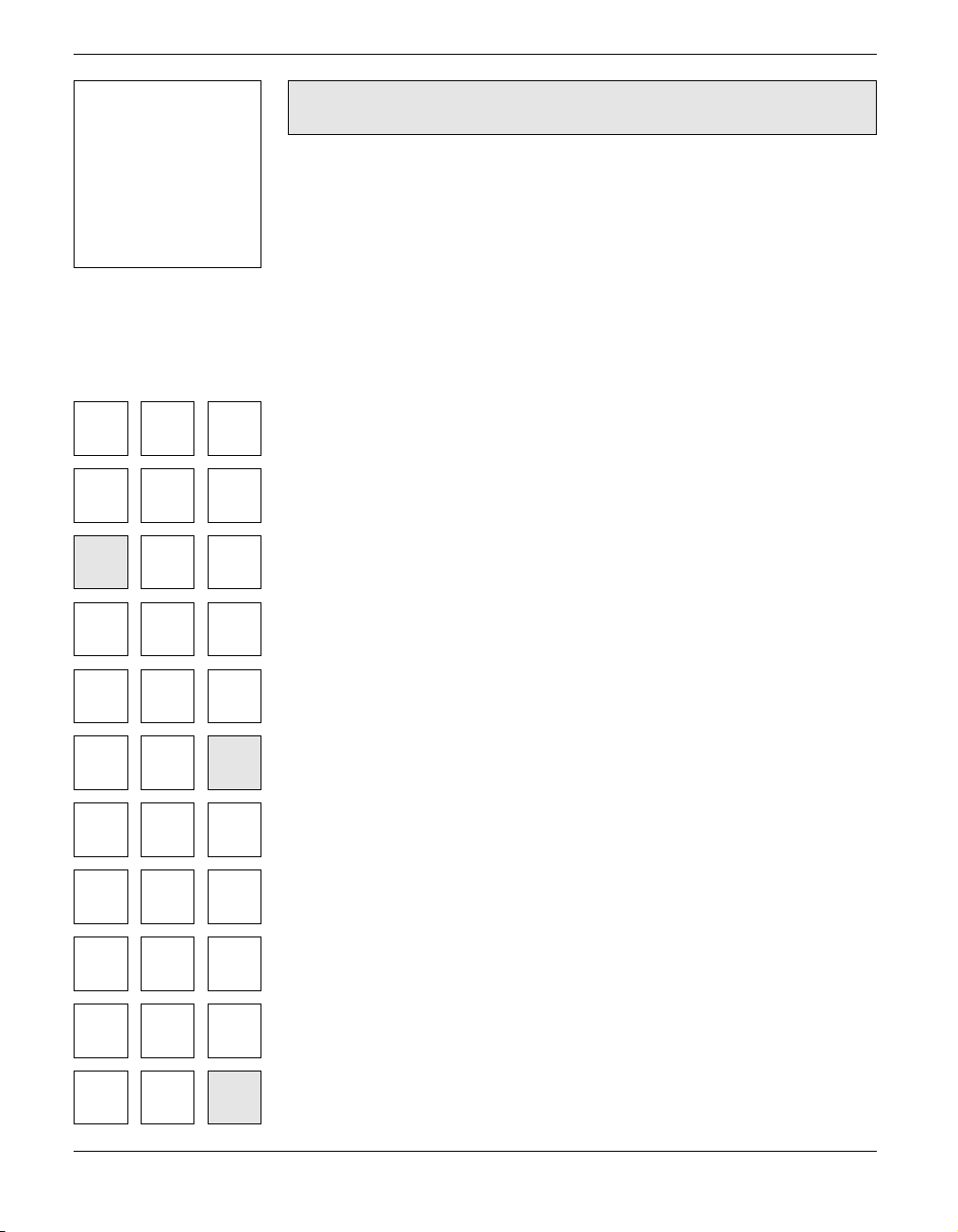
carries one or more of three safety symbols, as shown in Figure S–1.
These symbols appear next to those input and output connectors that
can be directly connected to human subjects.

Safety Notes vii
The three symbols are:
•
BF (body protected) symbol
. This means that the input
connectors are suitable for connection to humans provided there is
no direct electrical connection to the heart.
•
Warning symbol
. The exclamation mark inside a triangle means
that you should consult the supplied documentation (you’re
reading it) for operating information or cautionary and safety
information before using the device.
•
CF (cardiac protected) symbol
. (Appears on some models of Bio
Amp, and every BP Amp.) This means that the input connectors
are suitable for connection to humans even when there is direct
electrical connection to the heart.
Cleaning and Sterilisation
This system is not supplied with materials or components likely to
need sterilisation. If you need to clean peripherals likely to be in
contact with different subjects, they can be cold-sterilised with an
appropriate sterilising agent. No part of the system can be autoclaved.
Storage
It is recommended that the hardware be kept below 40
°
C and above
0
°
C in a moisture-free or low-humidity environment when not in use
(storage only). Electronic components are susceptible to corrosive
substances and atmospheres, so it is also advisable to keep the system
away from laboratory chemicals.
Warning symbol: see
documentation
BF symbol: Body-
protected equipment
!
CF symbol: Cardiac-
protected equipment
Figure S–1
Equipment safety symbols on
ADInstruments devices
designed for safe connection
to humans

viii
PowerLab Owner’s Guide
Preventative Inspection and Maintenance
Both PowerLab systems and ADInstruments front-ends are
maintenance free and do not require periodic calibration or
adjustment to ensure medical safety. Internal diagnostic software
performs system checks during power up and will report errors if a
significant problem is found.
There is no need to open the instrument for inspection or
maintenance, and doing so within the warranty period will void the
warranty.
If you so wish, your PowerLab system can be periodically checked for
basic medical safety by using an appropriate medical safety testing
device. Tests such as earth leakage, earth bond, insulation resistance,
patient leakage and auxiliary currents and power cable integrity can
all be performed on the PowerLab system without having to remove
the covers. You should follow the instructions for the testing device if
performing such tests.
If the PowerLab system is found not to comply with such testing you
should contact your PowerLab dealer to arrange for the equipment to
be checked and serviced. You should not attempt to service the device
yourself.
PowerLab Owner’s Guide
1
CHAPTER ONE
1
Overview
Your PowerLab recording unit, together with a range of specialised
application programs, provides a versatile data recording and
analysis system when used with a Windows or Macintosh computer.
This chapter provides an overview of the PowerLab system and
describes the basic features, connectors, and indicators of the SP
series PowerLabs: the PowerLab/4
SP
, PowerLab/8
SP
, and
PowerLab/16
SP
.

2
PowerLab Owner’s Guide
How to Use this Guide
This owner’s guide describes how to set up and begin using your
PowerLab recording unit. The chapters provide an overview of the
PowerLab system (the combined software and hardware package),
and a more detailed look at the features of your recording unit and its
connection to your computer. The appendixes provide technical
information about the recording unit, and solutions to problems. At
the end of this guide is a glossary of hardware terms, an index, and
warranty information.
The specifications and diagrams included in the appendixes are there
to help the more technically minded to understand what the
PowerLab can and cannot do, but this is not a service manual: only an
authorised ADInstruments distributor should attempt repairs. If you
modify the recording unit yourself, you void any rights you have
under warranty.
The user’s guides for the Chart and Scope application programs
provide detailed information on the software side of the PowerLab
system and its uses in acquiring, storing, and analysing data. Read
them after you have connected the PowerLab to your computer.
First, Check Your PowerLab!
Please do not attempt to connect the PowerLab to a power outlet or
computer or turn it on until you have read the first two chapters of
this owner’s guide, and have checked it as described below.
1. Check that all items in the accompanying packing list are
included in the box.
2. Check that there are no obvious signs of external damage to the
PowerLab.
3. Check that there are no obvious signs of internal damage, such as
rattling. Pick the PowerLab up, tilt it gently from side to side, and
listen for anything that appears to be loose.
4. Check that the correct voltage for your country is shown on the
back of the unit. Your PowerLab should be delivered with the
Ce manuel convient aux modèles suivants
2
Table des matières
Autres manuels ADInstruments Équipement d'enregistrement

Manuels Équipement d'enregistrement populaires d'autres marques


Strymon
Strymon NIGHTSKY Manuel utilisateur

Mitsubishi Electric
Mitsubishi Electric 16CH DIGITAL RECORDER DX-TL5000U Manuel utilisateur

Tews Technologies
Tews Technologies TPMC465 Manuel utilisateur

Honeywell
Honeywell Excel 50 Manuel utilisateur

SeaLevel
SeaLevel COMM+8.LPCI Manuel utilisateur

Arturia
Arturia AUDIOFUSE STUDIO Manuel utilisateur


