
ADEMCO 5110XM Manuel utilisateur

F
Fi
ir
re
e
A
Al
la
ar
rm
m
C
Co
on
nt
tr
ro
ol
l/
/C
Co
om
mm
mu
un
ni
ic
ca
at
to
or
r
User's Manual
5110XM
N8028 4/96

–2–
TABLE OF CONTENTS
SYSTEM OVERVIEW.................................................3
General...................................................................3
Zones.....................................................................3
Fire & Emergency Protection....................................4
Alarms.....................................................................4
Memory of Alarm......................................................4
ABOUT THE BUILT-IN INDICATORS............................5
ABOUT THE OPTIONAL KEYPADS............................7
General...................................................................7
Keypad Displays......................................................7
FUNCTIONS OF THE REMOTE KEYPAD.....................8
FIXED-WORD KEYPAD DISPLAYS..............................9
REMOTE KEYPAD USER CODES............................10
General.................................................................10
To Assign, Change, or Delete User Codes..............10
REMOTE KEYPAD EMERGENCY KEYS....................11
Using Emergency Keys..........................................11
Emergency Key Programmed Functions.................12
NORMAL STANDBY OPERATION.............................13
FIRE ALARM PROTECTION......................................14
General.................................................................14
In case of Fire ........................................................14
Silencing and Resetting a Fire Alarm.......................15
EMERGENCY ALARMS............................................16
General.................................................................16
Silencing and Resetting an Emergency Alarm..........16
BYPASSING PROTECTION ZONES..........................17
SUPERVISORY CONDITIONS...................................18
General.................................................................18
Silencing and Resetting a Supervisory Indication.....18
TROUBLE CONDITIONS...........................................19
ACTIVATING A FIRE DRILL TEST..............................21
QUICK GUIDE TO SYSTEM FUNCTIONS ...................22
SUMMARY OF AUDIBLE/VISUAL NOTIFICATION ......23
PROTECTION ZONES LIST......................................24
FCC STATEMENTS..................................................25
LIMITATIONS STATEMENT ......................................27
SERVICING INFORMATION.......................................28
WARRANTY...............................................Back Cover
This manual is a step-by-step guide that will acquaint you with the system's features and benefits. It defines the
components and their functions, describes their operation, and instructs you with normal and emergency
procedures.
Keep this manual in a convenient place so that you can refer to it as necessary.

–3–
SYSTEM OVERVIEW
General Congratulations on your ownership of an Ademco Alarm System. You've made a
wise decision in choosing it, for it represents the latest in alarm protection
technology today, including microcomputer technology to monitor all system status.
Ademco is the world's largest manufacturer of alarm systems and millions of
premises are protected by Ademco systems.
Your system is a UL Listed commercial fire alarm control/communicator. It monitors,
on an around-the clock basis, the various fire alarm warning, emergency alarm
warning and fire sprinkler system supervisory sensors that have been installed in
your system. When the control detects an alarm, supervisory, or trouble condition,
it automatically triggers an on-premises warning indication and transmits a message
to a central station over the telephone line so that appropriate action can be taken.
The control features a built-in warning buzzer and LED indicators which provide
the on-premises warning indication. In addition, your system may include an
optional remote keypad and/or optional external alarm warning sounders which will
provide additional on-premises warning indications. Please disregard references to
these devices in the text that follows, if they were not installed in your system.
Zones Your system has five protection zones. Your installer has assigned each of your
system's sensing devices to one of these zones. For example, warehouse smoke
detectors may have been assigned to zone 01, a fire sprinkler water valve
supervisory switch may have been assigned to zone 02, etc.. If a remote keypad
was installed in your system, it will display these zone numbers when an alarm,
supervisory or trouble condition is detected, so that the nature and location of the
fault can be pinpointed..

–4–
SYSTEM OVERVIEW
Fire & Emergency
Protection The fire and emergency protection portions of your system are always on and will
sound an alarm if an alarm condition is detected.
Alarms When an alarm occurs, the control's buzzer, the keypad and external sounders will
sound, and a message at the keypad will identify the zone(s) causing the alarm. In
addition, an alarm message will be sent to the connected central monitoring station.
You may stop the sound by pressing the SILENCE/RESET button at the control,
or by entering the OFF sequence (user code + OFF key) at your keypad .
Memory Of Alarm When an alarm, supervisory or trouble condition occurs, the keypad displays the
number(s) of the zone(s) that caused the problem, and displays the type of
condition present (ex. Fire, Alarm, Supv., Check). The display remains until it is
cleared by entering the OFF sequence (user code + OFF key) a second time or
by pressing the SILENCE/RESET button a second time if no keypad is present.

–5–
ABOUT THE BUILT-IN INDICATORS
The LED indicators, SILENCE/RESET button and WARNING buzzer (shown below) are located on the
control's main board inside the control's enclosure. The AC POWER, BATTERY TROUBLE,
COMMUNICATION FAIL, LINE DEFAULT and SILENCED LED indicators are visible through a viewing
window on the door of the enclosure. The enclosure door must be opened with the supplied key to gain access
to the SILENCE/RESET button.
LED Indicators
AC POWER
(GREEN)
BATTERY TROUBLE
(YELLOW)
COMMUNICATION FAIL
(YELLOW)
LINE FAULT
(YELLOW)
SILENCED
(YELLOW)
SILENCE/RESET
BUTTON
BUZZER
BACKUP DIALER
LINE SEIZE MAIN DIALER
LINE SEIZE
AC POWER.............................Lights when AC power is present.
Turns off when AC power is low or not
present and system is operating from
battery power.
BATTERY TROUBLE.................Lights when battery power is low or
disconnected. Turns off when battery
is OK.
COMMUNICATION FAILURE.......Lights when attempts to transmit a
message to the central station have
failed. Remains unlit when there are
no problems with central station
message transmission.
LINE FAULT ............................Lights when either the main or back-
up phone lines are faulted. Remains
unlit when both phone lines are okay.
SILENCED..............................Lights when the built-in warning
buzzer, the remote keypad buzzer
and external alarm sounders have
been silenced. Otherwise remains
unlit.

–6–
Warning Buzzer Produces slow on/off pulsing sound for fire alarms, steady sound for
emergency alarms, and rapid on/off pulsing sound for supervisory and
trouble conditions.
Silence/Reset Button Press to silence the built-in warning buzzer, the remote keypad warning
buzzer and the external alarm sounder. A second press resets faulted smoke
detectors and resets LED indicators if associated fault conditions have been
corrected.
Main Dialer Line Seize Lights when control is transmitting a message to the central station on the
main phone line.
Backup Dialer LIne Seize Lights when control is transmitting a message to the central station on the
backup phone line.
–7–
ABOUT THE OPTIONAL KEYPADS
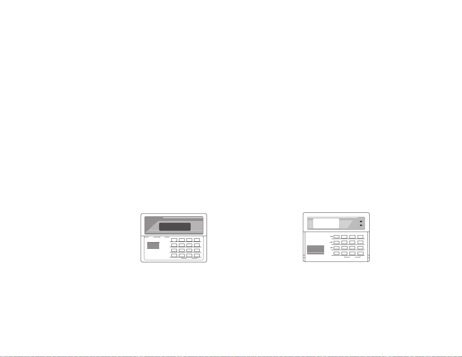
General The keypads feature a telephone style (digital) keypad and a Liquid Crystal
Display (LCD) which shows the nature and location of all occurrences.
The keypads feature a built-in sounder which emits the same alarm sounds as the
control's built-in warning buzzer during alarm conditions.
The keypad's display screen displays the same indications as the control's built-in
LED indicators, and in addition, displays the zone number of faulted zones as well
as the type of fault (i.e. alarm, supervisory or trouble) present. The telephone
style keypad keys allow entry of commands for silencing the warning sounds,
resetting faulted smoke detectors, activating various system tests, etc.
Keypad Displays There are two basic types of keypad displays, Alpha and Fixed-Word, either of
which may have been used in your system.
•Alpha Keypad Displays feature a 2-line, 32 character alphanumeric Liquid
Crystal Display (LCD) which can display the nature and location of all
occurrences in friendly English.
•Fixed-Word Keypad Displays are functionally similar to the Alpha Keypads,
except that their LCD display uses pre-designated (fixed) words to identify the
nature and location of occurrences.
Unless stated otherwise, all commands and procedures described herein apply
equally to all keypads.
Alpha
Keypad
1 2 3
A
4 5 6
B
7 8 9
C
*
0
#
D
OFF AWAY STAY
MAX TEST BYPASS
INSTANT CODE CHIME
READY
READYARMED
PANIC
OFF AWAY STAY
MAX TEST BYPASS
INSTANT CODE CHIME
READY
123
654
897
0
*
#
Fixed-Word
Keypad
ARMED
READY
A
B
C
PANIC
1 2 3
4 5 6
7 8 9
*0 #
OFF AWAY STAY
MAX TEST BYPASS
CODE CHIME
READY
INSTANT

–8–
FUNCTIONS OF THE REMOTE KEYPAD
1. DISPLAY WINDOW: Displays zone number and system
status messages.
2. 1OFF Key: Silences audible alarm, supervisory and
trouble sounds, and clears visual display after
problem's correction.
3. 6BYPASS Key: Removes individual protection zones
from being monitored by the system.
4. 8CODE Key: Used to assign additional 4-digit user
codes.
5. #Key: Used to activate fire drill.
(enter user 2's code + # + 69)
6. 0–9 Keys: Used to enter your 4-digit user code,
which must be entered before pressing the OFF,
BYPASS, CODE or [#] keys.
7. READY INDICATOR: Not used with this system.
8. ARMED INDICATOR: Not used with this system.
9. INTERNAL SOUNDER: Sound is:
slow on/off pulsing
for
fire alarms,
steady dual-tone
for emergency alarms,
and
rapid on/off pulsing
for supervisory and trouble
conditions.
10. A, B , C EMERGENCY Keys: Your installer may
have programmed these keys for manual activation of
fire or emergency alarms.
Note:
Other keys may be
available for emergency functions (see REMOTE
KEYPAD EMERGENCY KEYS section).
IMPORTANT!: When entering codes and commands, se-
quential key depressions must be made within 2 seconds of one
another. If 2 seconds elapses without a key depression, the
entry is aborted and must be repeated from its beginning.
1 2 3
A
4 5 6
B
7 8 9
C
*
0
#
D
OFF AWAY STAY
MAX TEST BYPASS
INSTANT CODE CHIME
READY
READYARMED
PANIC
TYPICAL ALPHA KEYPAD
Fixed-Word Keypads are functionally similar,
except for screen displays.
1
2
3
10
7
8
9
4
5
6

–9–
FIXED-WORD KEYPAD DISPLAYS
FIRE Appears when a fire alarm is detected. Accompanied by a display
of the zone # in alarm.
ALARM Appears when any type of alarm is detected. "FIRE" also appears
when a fire alarm is detected. Accompanied by a display of the
zone # in alarm.
SUPV Appears when a fire sprinkler system supervisory condition is
detected. Accompanied by a display of the zone # having the
supervisory condition.
CHECK Appears when a fire zone wiring fault is detected at any time. Also
appears when certain system problems such as phone line
problems are detected. Accompanied by a display of the zone # in
trouble.
AC Appears when AC power is present.
ALARM
AWAY
BYPASS
STAY
SUPV NO AC
TEST
NOT READY
CHIME BAT
FIRE CHECK INSTANT
FIXED-WORD DISPLAY
NO AC Appears when AC power is low, or not present. System is operating from backup battery power.
BAT Appears when backup battery is low or disconnected.
TEST Appears when the system is operating in one of its test modes (such as the fire drill test mode).
BYPASS Appears when one or more zones have been bypassed and are no longer operational.

–10–
REMOTE KEYPAD USER CODES
General If your system has a remote keypad installed, your installer will have programmed
a 4-digit user code (known as User Number 2 code) that can be entered at your
keypad to silence/reset alarms, bypass protection zones and activate the fire drill
test. This code may also be used to assign up to four other user codes (known as
User Number 3–6 codes).
The User Number 3–6 codes are intended for users who need limited and/or
temporary control over system operation. These codes can perform the same
functions as the User Number 2 code
except
for assigning user codes and
activating the fire drill test.
To Assign, Change, or
Delete
User Codes
User Number 2 can change, but not delete, his/her own code and can assign,
change, or delete codes for User Numbers 3–6.
User Numbers 3–6 cannot assign, change, or delete user codes.
1. Enter the User Number 2 code and press the CODE key.
2. Enter a single-digit User Number (2–6) for the user whose code is to be
assigned, changed, or deleted.
3.
If
assigning or changing a user's code,
enter the new 4-digit code for that
user. The keypad will beep once, indicating that the new code has been
accepted.
If deleting a user's code,
perform steps 1 and 2 and then stop. After a few
moments the keypad will beep once, indicating that the existing code has been
deleted.
Autres manuels pour 5110XM
1
Table des matières
Autres manuels ADEMCO Panneau de contrôle

ADEMCO
ADEMCO 6127 Manuel utilisateur

ADEMCO
ADEMCO VISTA-20SE Manuel utilisateur

ADEMCO
ADEMCO Vista 15 Manuel utilisateur

ADEMCO
ADEMCO Ademco -10SE Manuel utilisateur

ADEMCO
ADEMCO LST700 Series Manuel utilisateur

ADEMCO
ADEMCO VISTA Manuel utilisateur

ADEMCO
ADEMCO Galaxy 16 Guide de démarrage rapide

ADEMCO
ADEMCO Vista-20HWSE/SE Manuel utilisateur

ADEMCO
ADEMCO Ademco VISTA-40 Manuel du propriétaire


