953.446UK User Manual
Additional connectors include an SMA socket for a Bluetooth antenna. Carefully screw the supplied mini antenna onto this socket.
An F-connector (39) provides the option of connecting to an FM aerial for the radio tuner function of the internal media player.
A 24V screw terminal (37) may be connected from a fire or emergency panel that can send a 24V signal when triggered, which will
mute all channels except the call station and paging microphone.
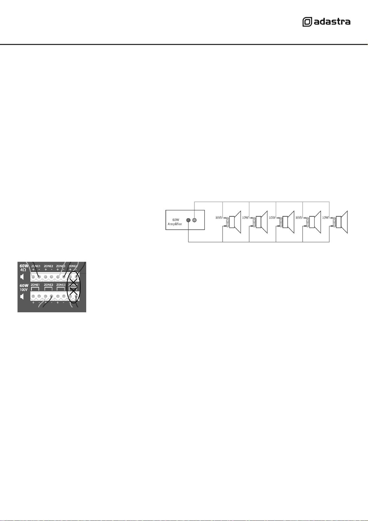
Speaker connection
Loudspeakers should be connected to the RM4460 via screw terminals on one of 2 removable modular connectors.
If the speaker(s) being connected is not 100V type, use the terminal block marked “4Ω” for this channel (14).
Connect + and –wires to each speaker as indicated, ensuring that there is no chance of strands shorting across terminals.
Important: Ensure that the load is no lower than 4Ωfor each output. This can be…
1 x 4Ω speaker 1 x 16Ωspeaker
1 x 8Ω speakers 2 x 16Ωspeakers wired in parallel (8Ω)
2 x 8Ω speakers wired in parallel (4Ω) 3 x 16Ωspeakers wired in parallel (5.3Ω)
4 x 16Ωspeakers wired in parallel (4Ω)
Ensure that the connected speakers can handle 60W from each output.
If the speaker(s) being connected to an output channel
are 100V type, use the terminal block marked “100V”for
this output channel. When connecting multiple 100V
speakers to this output, connect all speakers in parallel
and ensure that the total load is below 54W.
The wattage of each speaker can sometimes be
adjusted via tappings on the speaker (check the
speaker’s documentation if unsure)
DO NOT connect to both 4Ωand 100V terminals for any individual output channel
DO NOT mix 4Ωand 100V speakers on any single output.
THERE SHOULD BE NO CONNECTION MADE VERTICALLY ABOVE OR BELOW ANY OTHER
When all signal and speaker connections are made, connect the rear IEC inlet (16) to the mains using the supplied mains lead
(or an equivalent approved type).
Ensure that the supply voltage is correct for this equipment and that the mains outlet is switched on.
Operation
When all signal and speaker connections are made, power up the RM4460 and gradually increase the LEVEL control of Zone 1 part way
for testing. You can repeat the same process for the remaining 3 zones after all inputs have been adjusted.
If a mic is connected to input 1 (34), press in the Zone 1 select button (10), speak into the mic and gradually increase the level (9)
The signal LED should light in response to the speech and the sound should be heard through speakers connected to Zone 1.
For any connections to inputs 2 and 3, repeat the above process whilst speaking into the mic or playing the audio for that input.
When the required level has been set for each of inputs 1, 2 and 3, the tone may be adjusted using BASS & Treble controls (8, 11, 14)
Turning the Bass control left from 12 o’clock cuts low frequencies, turning this control right from 12 o’clock boosts low frequencies.
Turning the Treble control left from 12 o’clock cuts high frequencies, turning this control right from 12 o’clock boosts high frequencies.
If an audio source is connected to the line input, press in the Zone 1 select button (7) and press in the MEDIA/LINE select button (5)
Play the audio, whilst gradually increasing the LEVEL control (6) until the required level.
This input can be switched over to the internal media player when the select button (5) is in the “out”position.
More information about the media player operation is detailed below.