ACU-RITE ENC 150 Manuel utilisateur
ENC 150™
ACU-RITE
®
REFERENCE MANUAL
Page
Introduction .............................................................................. 2
Mounting Preparation............................................................... 3
Mounting Information ............................................................... 4
Encoder Dimensions................................................................ 5
Backup Spar Dimensions ........................................................ 6
Mounting Requirements........................................................... 7
Typical Mounting (s)................................................................. 8
Encoder Installation Procedure ............................................... 9
Page
Spar Installation Procedure ..................................................... 11
Checking your Installation........................................................13
Electrical Shielding ................................................................ 14
Troubleshooting ..................................................................... 15
Mechanical Specifications ..................................................... 16
Output Signals and Pin-Outs ................................................. 17
Electrical Specifications ......................................................... 18
The ACU-RITE Warranty ....................................................... 19
•Installation brackets and kits are available.
• Your Authorized ACU-RITE Distributor can assist you with your
selection of these for your installation.
1ACU-RITE
®
Motor mount
Reading Head
bracket
Horizontal mt.
bracket
Extension
bracket
Side mount
bracket
Rear mount
bracket
ENC150 Table of Contents

B
C
A
E
D
F
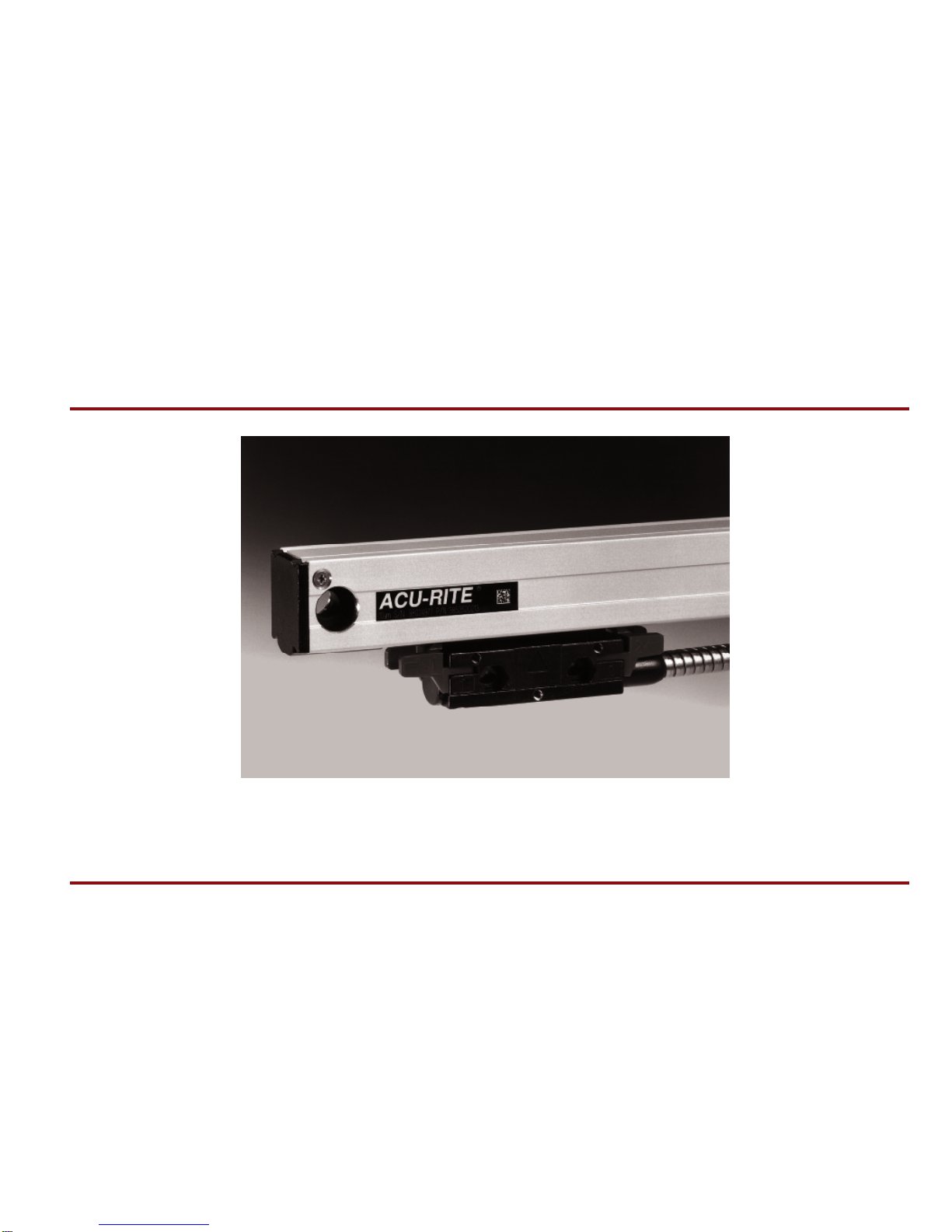
The ENC 150 precision glass scale linear encoder provides the
accuracy and reliability of an ACU-RITE measuring system with
digital output (analog output available). Features and options
include:
•Resolutions of .5, 1, 2, 5, or 10 µm.
•Accuracy grades of
±
3, and ± 5 µm / 1000 mm.
• Vinyl or Armor cables of 2, 5, 10, 15 and 20 ft. length.
•Fasteners, center supports, and backup spars.
•Brackets and accessories.
Contact your Authorized ACU-RITE Distributor for assistance with
the selection of product options and accessories.
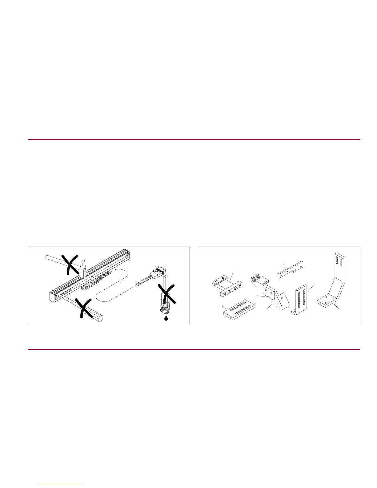
A) ENC 150 Linear Encoder
B) Backup Spar
C) Reference Manual
D) Cable Mounting Hardware
E) Linear Encoder Mounting Hardware
F) Backup Spar Mounting Hardware
ACU-RITE
® 2
Introduction ENC 150
C
A
Contents
< 60”
D
E
Contents
> 65”
Forfuture ordering information or warranty service,recordthelinear
encoder catalog number located on the scale assembly tag, and
the serial number from the reading head tag.
Catalog No. Serial No.
Axis # 1: _______________ __________________
Axis # 2: _______________ __________________
Axis # 3: _______________ __________________
Axis # 4: _______________ __________________
Date of purchase: _______________ __________________
Distributor: ____________________________________
Address: ____________________________________
Telephone: ____________________________________

Please follow these preparation guide lines.
•Understand your mounting requirements.
•Mount with lip seals down and away from the work area.
•Brackets should be kept as short as possible and rigid.
•Surfaces must be in good condition, clean, and free of dirt.
Remove paint from machined mounting surfaces.
•Alignment brackets must not be removed until instructed.
•Machine travel can not exceed the encoder measuring length.
•Either limit machine travel or obtain correct length scale.
•Determine cable exit direction before installing.
• To change cable exit direction; remove base and rotate 180°.
•Never mount with lip seals upward or towards work area.
3ACU-RITE
®
ENC150 Mounting Preparation
“L” = Measuring length
+ 1.75” nominal
over travel
“L”
1.150
1.150
Cable direction
Rotate reading head
base 180°
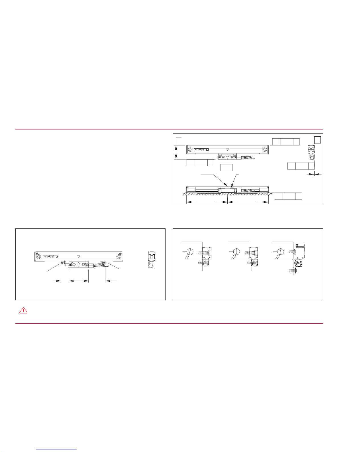
Use this information to plan your Linear Encoder installation.
•Mountthe linear encoders close to machineguidewaystoensure
system accuracy.
•Onesideofthelinearencoderaddressesflushmountingsurfaces,
and the opposite side addresses offset mounting surfaces.
•If space between the reading head and the mounting surface
exceeds .18”, use a spacer or mounting bracket to reduce space.
•ACU-RITEbracketkitinstructionsprovide step by step installation
proceedures.
• Tolerances of .010” TIR apply to all mounting dimensions.
•Center support mounting surface required for 24” through 60”
linear encoder measuring lengths mounted without a spar.
•Allow clearance for alignment bracket removal.
•Alignment brackets must not be removed until instructed. •Usereadingheadlevelingsetscrewswhensurfacesarenot flush.
•Reading head bracket required for a space >.18”.
ACU-RITE
® 4
Mounting Information ENC150
Scale case
Flush
mounting Offset
mounting Backup spar
mounting
-A- = Machine Travel
Reading head
B
Equal Equal
1.826 ±.010 [46.5]
// .010 A
// .010 A
// .010 B
// .010 A
// .010 A
0.0 ± .010
Move bracket past
the cable strain relief
Alignment bracket removal clearance
1.0
[25mm] 1.38
[35mm]
Alignment
bracket
Alignment
bracket
5ACU-RITE
®
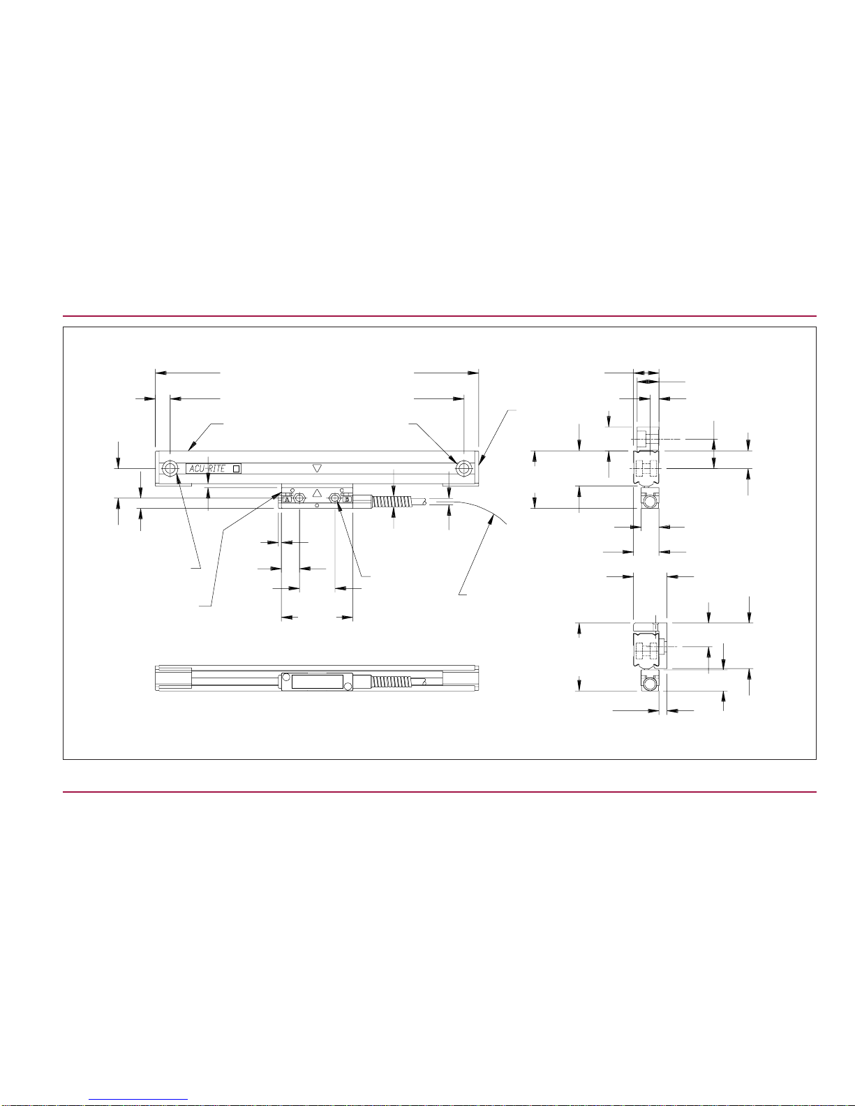
ENC150 Encoder Dimensions
Measuring length + 6.375
Measuring length + 5.437
.469
[11.9]
.944
[24.0]
.320
[8.1]
∅ .500 C’Bore
∅ .313 Thru
Reading Head
assembly 2.250
[57.1]
1.125
[28.6]
.56
[14.4]
.100
[2.5]
∅ For 8-32
(or M4) SHCS
mounting
screw
.32
[8.4]
Armor
.20
[5.2]
Vinyl
1.25 [32]
Min. bend rad.
Max. nominal linear encoder over travel 1.825
Published over travel 1.75”
.810
[20.6]
.285 [7.2]
1.826
[46.4]
1.12
[28.5]
End Cap
Mounting hole
Scale case .562
[14.3]
.570
[14.5]
.810
[20.5] 1.060
[27.0]
2.148
Ref.
[54.6]
.250
[3.4] .660
[16.8]
1.440
[36.6]
.750
[19.0]
.121
[3.11]
With Backup
Spar
.937
[23.8]
.700
[17.8]
.750
[19.0]
ACU-RITE
® 6
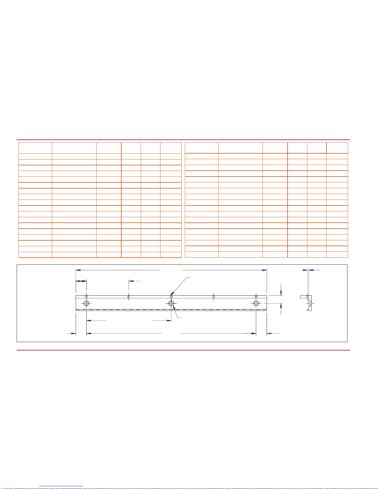
Backup Spar Dimensions ENC 150
“A” ± .015
“A” ± .005
“L” ± .015
5.000 typ. ± .015
Non
Accumulative
“B” typ. ± .015
Non Accumulative “A” Ref.
.750 ± .005
.110 ± .005
M4 Thru
∅.312 Thru
∅.500 C’Bore x .160 Dp.
“X” No. of holes
“E”
Backup spar
Part Number Linear Encoder
Measuring Length LA
X No.
Places B
385102-000 2 8.312 1.656 2 5.000
385104-000 4 10.312 2.656 2 5.000
385106-000 6 12.312 1.156 2 10.000
385108-000 8 14.312 2.156 2 10.000
385110-000 10 16.312 3.156 2 10.000
385112-000 12 18.312 4.156 2 10.000
385113-000 13 (Special) 19.312 1.44 2 16.43
385114-000 14 20.312 5.156 2 10.000
385116-000 16 22.312 1.156 3 10.000
385118-000 18 24.312 2.156 3 10.000
385120-000 20 26.312 3.156 3 10.000
385122-000 22 28.312 4.156 3 10.000
385124-000 24 30.312 5.156 3 10.000
385126-000 26 32.312 1.156 4 10.000
385128-000 28 34.312 2.156 4 10.000
385130-000 30 36.312 3.156 4 10.000
385131-000 31.5 38.030 4.015 4 10.000
385132-000 32 (“E” 34.812) 35.687 .437 4 11.604
Backup spar
Part Number Linear Encoder
Measuring Length LA
X No.
Places B
385135-000 35 (“E” 40.437) 41.312 .437 5 10.109
385136-000 36 42.312 1.156 5 10.000
385138-000 38 44.312 2.156 5 10.000
385140-000 40 46.312 3.156 5 10.000
385142-000 42 48.312 4.156 5 10.000
385148-000 48 54.312 2.156 6 10.000
385152-000 52 58.312 4.156 6 10.000
385154-000 54 60.312 5.156 6 10.000
385160-000 60 66.312 3.156 7 10.000
With Encoder 65 71.312 5.656 7 10.000
With Encoder 72 78.312 4.156 8 10.000
With Encoder 78 84.312 2.156 9 10.000
With Encoder 84 90.312 5.156 9 10.000
With Encoder 90 96.312 3.156 10 10.000
With Encoder 100 106.312 3.156 11 10.000
With Encoder 110 116.312 3.156 12 10.000
With Encoder 120 126.312 3.156 13 10.000
Mounting options can be adapted to machine mounting surfaces
using spacers, standoffs, or leveling set screws.
•Measuring length and mechanical configuration of your machine
determine your options.
•Backup spar mounting is an option but not required for lengths
up to 60”.
•Fastener lengths described on this page are included with the
encoder or the backup spar.
•Less than 24” : Use end mounting holes. • Over 60” :A backup spar is required.
7ACU-RITE
®
ENC150 Mounting Requirements
1/4-20 x 1” BHCS
& scale washer
(supplied)
End hole mounting
1/4-20 x 1/2” BHCS
and spar washer
(supplied)
Backup spar
mounting
•24” to 60” : Use end mounting holes with center support.
.94 [23.8]
1/4-20 x 1” BHCS
Typical (supplied)
1/4-20 x 3/4”
SHCS Linear
Encoder
washer
Center
support
End hole mounting
with center support
M4 x 8mm
SHSS
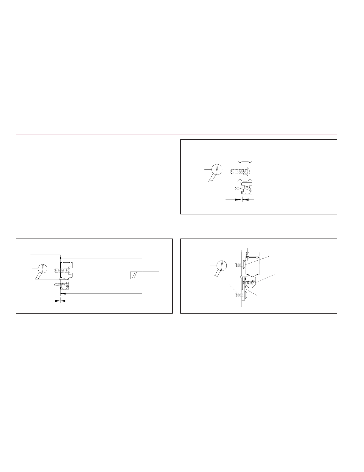
A variety of mounting conditions can be accommodated.
•The machine configuration determines the brackets required to
install the linear encoder.
•Three typical mounting conditions are shown; flush, offset, and
backup spar (as shown previously on page 4).
•The 8-32 SHCS fastener lenghts shown on this page are typical
to the trim length requirement of the 1” long fastener supplied.
•The 8-32 SHCS for mounting the reading head is a standard low
head style fastener.
•Mounting surfaces are offset.
•Installation without backup spar.
•Use leveling screws in place of spacers or shims.
•Mounting surfaces are flush within .005”.
•The reading head leveling screws are not required. •Flush or offset mounting surfaces with a backup spar.
•Bracket used to reduce head to mounting surface gap.
• Use reading head leveling set screws.
ACU-RITE
® 8
Typical Mounting (s) ENC 150
Backup spar with
bracket
Offset surfaces
1/4-20 x 1” BHCS
and encoder washer
8-32 x 3/4” SHCS (trim)
Flush surfaces
.005
0.0 ± .005
1/4-20 x 1” BHCS
with encoder washer
8-32 x 1” SHCS
Space of < .18” use reading head
leveling set screws.
1/4-20 x 1/2” BHCS
and spar washer
8-32 x 5/8” SHCS
(trim)
1/4-20 x 1/2” BHCS
and washer A space >.18”, use a spacer or
bracket (shown); <.18” use
leveling set screws.

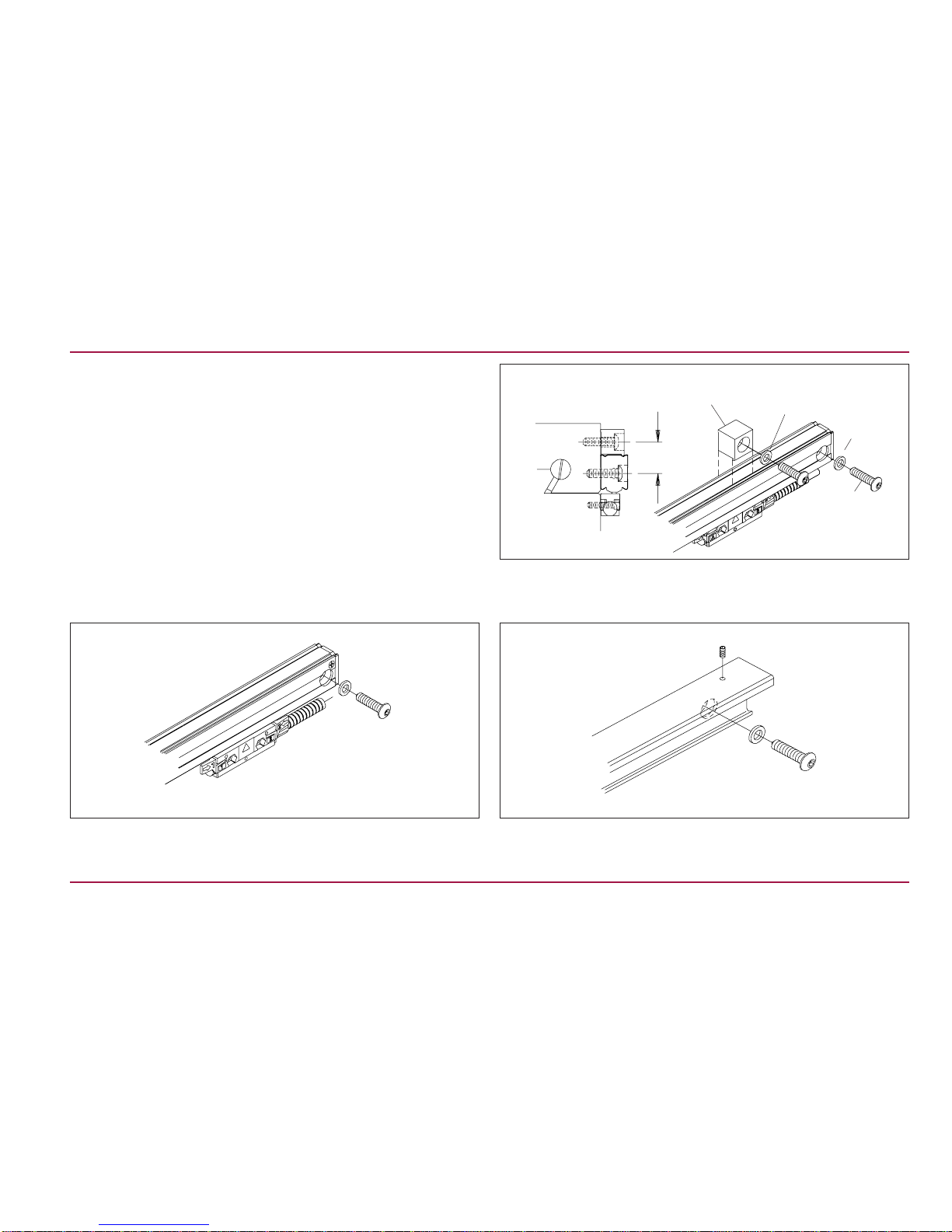
These steps apply to all encoder mounting conditions, if a spar is
being used, go to “Spar Installation Procedure” on page 11.
•ACU-RITEbracketkitinstructionssupercedethissection.
•Adjust drill depths and fastener lengths as required.
•When instructed on page 10: Adjust the leveling set screws as
follows:
1.Insert, but do not tighten 8-32 (M4) reading head screws.
2.Place a .001”-.003” shim between the leveling set screws and
mounting surface.
3.Adjust each set screw until a slight drag is felt on the shim.
4.Evenly tighten the 8-32 (M4) reading head mounting
screws.
•ContactyourAuthorizedACU-RITEDistributor should you require
additional assistance.
•Align the center marks on the reading head and scale assembly
by sliding the reading head and brackets along the case. •Locate the scale case so underside of endcaps are flush with the
axis parting line.
•Mark one end mounting hole location.
•Move the machine axis to its center of travel.
•Mark the axis for quick return to center.
•Configure the encoder cable exit direction (see page 3).
9ACU-RITE
®
ENC150 Encoder Installation Procedure
Scale case
Reading head assembly
Alignment
brackets (2)
C
L
Center mounting
axis
Mark center
of axis
C
L
Align top of scale case to
within .015” of -A-
-A- = Axis travel
Cable assembly Endcap
Scale case
Axis parting line
End mounting hole (typical)
Center marks
Table des matières
Autres manuels ACU-RITE Convertisseur de média

ACU-RITE
ACU-RITE ENC 150 Manuel utilisateur

ACU-RITE
ACU-RITE SENC 150 Manuel utilisateur

ACU-RITE
ACU-RITE SENC 150 Manuel utilisateur

ACU-RITE
ACU-RITE ENC 250 Manuel utilisateur

ACU-RITE
ACU-RITE ENC 250 Mode d’emploi

ACU-RITE
ACU-RITE SENC 150 Manuel utilisateur

ACU-RITE
ACU-RITE SENC 150 Manuel utilisateur

ACU-RITE
ACU-RITE SENC 150 Manuel utilisateur


