Acconeer A121 Manuel utilisateur

A121 Integration using STM32CubeIDE
User Guide

A121 Integration using STM32CubeIDE
Contents
1 Introduction 3
2 Getting Started with STM32CubeIDE 4
2.1 MCU/BoardSelection ............................................ 4
2.2 ProjectSetup ................................................. 5
2.3 PinConfiguration............................................... 6
2.3.1 PinConfigurationwithXE121.................................... 9
2.4 InterruptConfiguration ............................................ 10
2.5 GPIOConfiguration.............................................. 10
2.6 XE121SensorSelection ........................................... 11
2.7 XE121SingleSensorSetup.......................................... 11
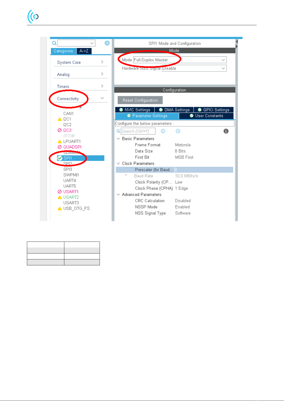
2.8 SPIConfiguration............................................... 12
2.9 CodeGeneration ............................................... 12
3 Configuring Project for Acconeer Software 14
3.1 AddingAcconeerSoftware.......................................... 14
3.1.1 Source-files.............................................. 14
3.1.2 Header-files.............................................. 14
3.1.3 Libraries ............................................... 14
3.2 ProjectSettings ................................................ 14
3.3 Adding Print Functionality with UART/USART . . . . . . . . . . . . . . . . . . . . . . . . . . . . . . . 15
3.3.1 FindSTM32BoardCOMport.................................... 15
3.3.2 StartandConfigurePuTTY ..................................... 15
4 HAL Integration File 18
4.1 Selecting the Appropriate HAL-integration File . . . . . . . . . . . . . . . . . . . . . . . . . . . . . . . 18
4.2 A121_SPI_HANDLE............................................. 18
4.3 SensorCrystalFrequency........................................... 18
5 Running a Radar Sensor Example 19
6 Troubleshooting and FAQ 20
6.1 ExampleFails................................................. 20
6.1.1 Sensor Creation Returns NULL . . . . . . . . . . . . . . . . . . . . . . . . . . . . . . . . . . . 20
6.1.2 ConfigCreationHardfaults...................................... 20
6.2 The Program is Stuck in HAL_Delay . . . . . . . . . . . . . . . . . . . . . . . . . . . . . . . . . . . . . 20
6.3 Troubleshooting SPI Communication . . . . . . . . . . . . . . . . . . . . . . . . . . . . . . . . . . . . 20
6.4 UARTProblems................................................ 21
6.5 LinkErrors .................................................. 21
6.6 HeapMemoryCorruption........................................... 21
7 Disclaimer 23
© 2022 by Acconeer AB - All rights reserved Page 2 of 23

A121 Integration using STM32CubeIDE
1 Introduction
In this document there will be a short guide with example on how to generate a project and setup the Acconeer software
in STM32CubeIDE.
The MCU board used as an example in this guide is a Nucleo-L476RG. We will show how to connect an XE121, including
the A121 radar sensor. There is some extra logic on the XE121 board to support multiple sensors that typically is not
present on boards with only one sensor. To show how a typical single sensor integration can be done, we have also
included some notes on how to use the XE121 in a single sensor setup.
STM32CubeIDE can be downloaded from the ST website at:
https://www.st.com/en/development-tools/stm32cubeide.html
This guide has been verified in both Ubuntu 20.04 and Windows with STM32CubeIDE 1.9.0
© 2022 by Acconeer AB - All rights reserved Page 3 of 23

A121 Integration using STM32CubeIDE
2 Getting Started with STM32CubeIDE
This section will cover how to setup a project in STM32CubeIDE, and make sure that the code works with the Acconeer
software.
Start STM32CubeIDE and click “Start new STM32 project”. The option is also available under “File →New →
STM32Project”.
Figure 1: Start new STM32CubeIDE project
When running on Linux/Ubuntu you might be asked about Connection Parameters, generally, you can skip this part by
selecting “No proxy”.
2.1 MCU/Board Selection
Search for the MCU or Board you are working with in the MCU Selector/Board Selector tab. In the example in this
document we use the board “NUCLEO-L476RG”. Start off by searching for “NUCLEO-L47” in the “Part Number
Search”-option at the top left in the Board Selector tab.
The board will show up in the “Boards list” at the bottom of the page. Click it. When clicking the board or MCU, you
will be given some information about it.
Make sure the “Nucleo-L476RG” board is selected and press the “Next”-button at the bottom of the page.
© 2022 by Acconeer AB - All rights reserved Page 4 of 23

A121 Integration using STM32CubeIDE
Figure 2: Target Selection
2.2 Project Setup
Select a name and location for your project and select the following options:
• Target language: C
• Target Binary type: Executable
• Target Project Type: STM32Cube
Finally, press the “Finish”-button at the bottom of the page.
© 2022 by Acconeer AB - All rights reserved Page 5 of 23

A121 Integration using STM32CubeIDE
Figure 3: Project Setup
Press “Yes” when you are asked if you want to initialize peripherals to their default mode.
Figure 4: Initialize Peripherals
Press “Yes” when you are asked if you want to open the STM32CubeMx perspective.
Figure 5: Open STM32CubeMX perspective
2.3 Pin Configuration
The Pinout is flexible – however it is important that the pins communicating with the radar have the right user labels and
that SPI is configured with “Full-Duplex Master”-mode.
In order to perform pin configuration you need to have the “.ioc”-file open that is named after your project.
© 2022 by Acconeer AB - All rights reserved Page 6 of 23

A121 Integration using STM32CubeIDE
The “LD2 [green Led]“ on the Nucleo board shares functionality with “SPI1_CLK“. Before we add SPI functionality we
need to remove the “LD2 [green Led]“ configuration from PA5. The pin configuration is removed by doing a left mouse
click on PA5 / “LD2 [green Led]“ and then selecting “Reset_State“.
Figure 6: Remove LD2 pin
The “B1 [Blue PushButton]“ on the Nucleo board is not used on our examples and can be removed. The pin configuration
is removed by doing a left mouse click on PC13 / “B1 [Blue PushButton]“ and then selecting “Reset_State“.
© 2022 by Acconeer AB - All rights reserved Page 7 of 23

A121 Integration using STM32CubeIDE
Figure 7: Remove B1 pin
In our example we activate SPI1 with “Full-Duplex Master”-mode by going into “Connectivity” in the “Pinout and
Configuration”-tab. Then by pressing “SPI1” the option of selecting mode is available, “Full-Duplex Master” is selected.
When doing this we get the SPI GPIOs:
© 2022 by Acconeer AB - All rights reserved Page 8 of 23

A121 Integration using STM32CubeIDE
Figure 8: SPI Setup
USER_LABEL NUCLEO PIN
SPI1_MOSI PA7
SPI1_MISO PA6
SPI1_SCK PA5
2.3.1 Pin Configuration with XE121
In order to set new GPIOs, you can left click the desired pin and selected the desired function of the pin.
The table below shows how the XE121 and the NUCLEO-board can be connected:
© 2022 by Acconeer AB - All rights reserved Page 9 of 23
Autres manuels pour A121
1
Table des matières
Autres manuels Acconeer Accessoires


