4O3A Station Genius v2 Manuel utilisateur

Station Genius v2
User Manual
Table of Contents
0. Introduction........................................................................................................................2
1. Device Overview................................................................................................................5
1.1 Front Panel..................................................................................................................5
1.2 Rear Panel...................................................................................................................6
1.2.1 Connectors...........................................................................................................6
1.2.2 Buttons...............................................................................................................10
1.2.3 DIP Swtic es.......................................................................................................11
2. Additional ardware..........................................................................................................13
2.1. Output Modules........................................................................................................13
2.2 USB Keyboard...........................................................................................................14
3. Software...........................................................................................................................15
3.1 Initial Setup................................................................................................................15
3.2 Device Settings..........................................................................................................46
1. Device Status..........................................................................................................49
2. CAT Configuration...................................................................................................50
3. Network Configuration.............................................................................................51
4. Ot er........................................................................................................................51
3.3 Button Types..............................................................................................................52
3.4 Output Modules.........................................................................................................53
3.4.1 Local Outputs.....................................................................................................53
3.4.2 Remote Outputs.................................................................................................54
3.5 Exclusive IDs.............................................................................................................55
3.6 Subgroups..................................................................................................................55
3.7 Split Signals...............................................................................................................56
3.8 Configuration Options................................................................................................57
3.9 Connection Options...................................................................................................58
3.10 FlexRadio Connection.............................................................................................59
3.12 Firmware Upgrade...................................................................................................60
Page 1

0. Introduction
Congratulations on your purc ase of t e Station Genius controller by 4O3A. Station
Genius is t e most complete, easy-to-use, amateur radio station controller available on t e
market today.
SG can be used as a single unit or it can be used in a network of multiple SG and ot er
devices, allowing for scalability in future s ack setups.
Here is an example of an InBand setup using Station genius and some ot er 4O3A
products.
Station Genius is primarily designed to be used wit a PC. T e user interface of t e SG
Windows app integrates seamlessly wit Win-Test logging software and ot er HAM apps.
⬆ Back to table of contents Page 2


1. Device Overview
1.1 Front Panel
Since version 2.0, most LEDs can be customized to indicate w atever configure. We will
go troug t e original design be ind t em, so you can get a feel for t e concept. Starting
from left:
1. BANDindicates current band in use.
2. M, X and Y are logical groups of up to 5 antennas. M is usually used for main
antennas.
3. S indicates split signals.
4. PTT indicates PTT.
5. MODE indicates w et er SG is being controlled by t e PC app or t e external
keyboard.
6. INH indicates t at t e device is in in ibit mode.
7. INT indicates t at t e device is in interlock mode.
8. TX indicates t at one or more transmitters are active in t e network.
9. SO2R R1 and R2 LEDs are not in use.
10.MAIN DISPLAY is a 2x16 c ar LCD for text messages.
⬆ Back to table of contents Page 4

1.2 Rear Panel
1.2.1 Connectors
Overview of connectors on t e back of t e device, starting from left:
1. PTT OUT, w ite RCA connector:
PTT output signal. Configured by jumpers. Jumpers to program t e
PTT Outputs are located below its RCA connector socket.
Unlike t e PTT DLY input, t ese outputs ave no delay.
T e RCA jack can be configured for eit er:
1. Closure to Ground (left position)
2. +12V DC on Transmit (rig t position)
T e top position is for normally open configuration.
T e bottom position is for normally closed configuration (s orted on
RX).
⬆ Back to table of contents Page 5

2. PTT DLY, yellow RCA connector:
PTT output signal wit delay. Configured by jumpers. Jumpers to
program t e PTT Delay Outputs are located below its RCA connector
socket.
T ese outputs include a programmable delay, for amplifier or
preamplifier sequencing, etc. Delay time is programmed from t e SG
Windows app.
T e RCA jack can be configured for eit er:
1. Closure to Ground (left position)
2. +12V DC on Transmit (rig t position)
T e top position is for normally open configuration.
T e bottom position is for normally closed configuration (s orted on
RX).
3. FS, black RCA connector:
PTT input from a foot switc . T is input is always looking for a closure
to ground on transmit.
Foot switc line is isolated wit an optocoupler.
4. PTT IN, black RCA connector:
Generic PTT input from an external device, suc as a foot
switc , relay, or line containing +5V or +12V DC.
PTT IN line is isolated wit wit an optocoupler.
5. INHIBIT, red RCA connector:
T e in ibit output signal, for blocking transmit capability of ot er
transmitters.
In ibit signal is +12V or GND. Jumpers for configuring t e
output signal are located below t e in ibit RCA socket.
⬆ Back to table of contents Page 6
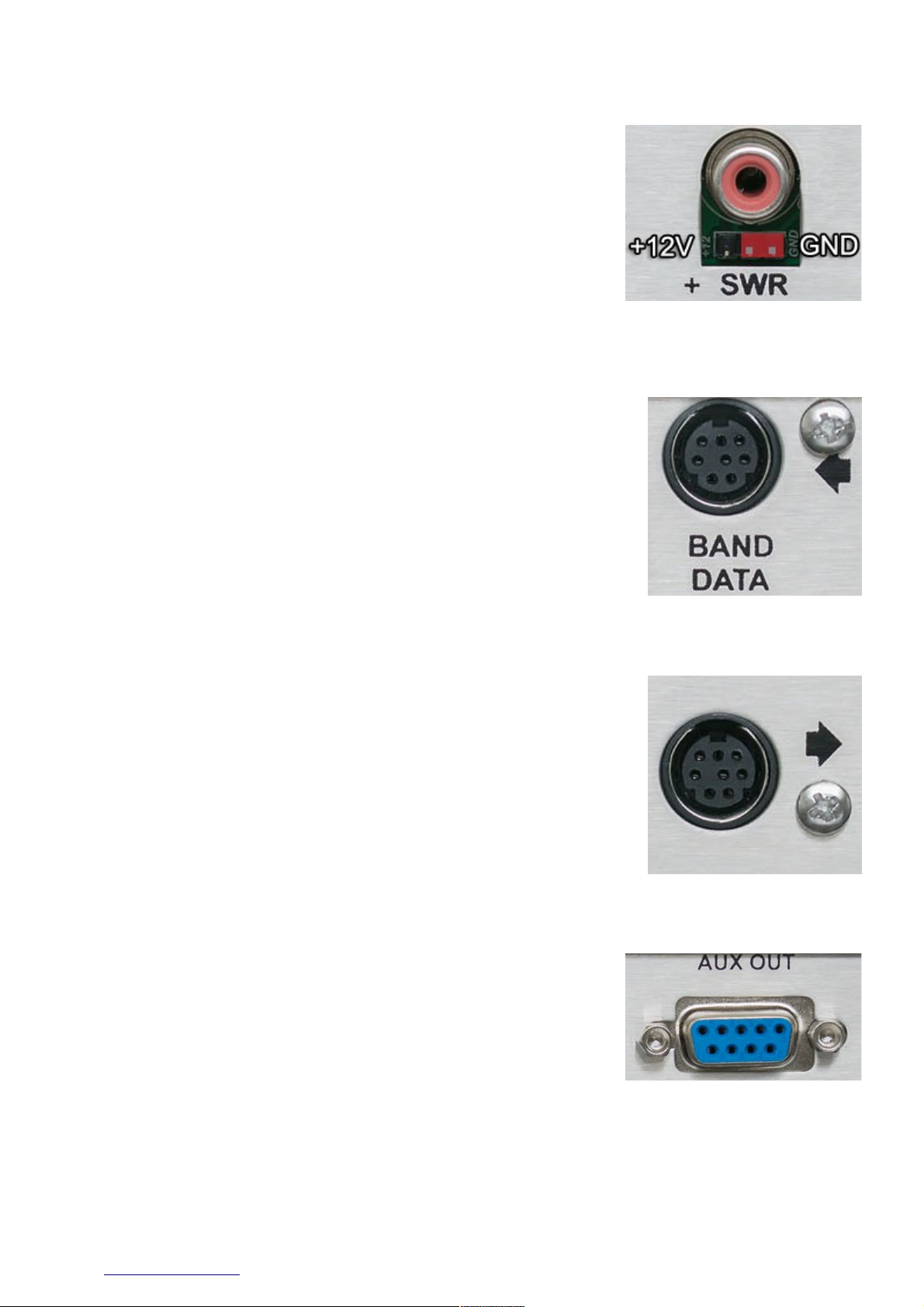
6. SWR, red RCA connector:
Hig SWR (or any ot er alarm state) input from an external
device (suc as an antenna analyzer, amplifier, etc.) to block t e
transmitter from putting out any power.
SWR alarm is expecting eit er +5V DC or a closure to GND.
Jumpers for configuring t e input signal are located below t e
SWR RCA socket.
SWR line is isolated wit an optocoupler.
7. BAND DATA IN, black RCA connector (arrow pointing towards t e connector):
T is DIN connector accepts Band Data signals from an external
device.
T e connector is directly compatible wit Yaesu Band Data jacks.
Band data in line is isolated wit optocoupler.
8. BAND DATA OUT, black RCA connector (arrow pointing away from t e connector):
T is DIN connector forwards Band Data for use wit linear
amplifiers or ot er devices requiring BCD data.
9. AUX OUT, DB9 connector:
T is DB9 female AUX socket is used to connect t e controller to
t e output module unit. It uses a pin to pin cable.
Cable as to ave GND on DB9 metal case.
⬆ Back to table of contents Page 7

10. Ethernet, RJ-45 connector:
For connecting SG to your local computer network. Multiple SG devices
communicate wit eac ot er using t e TCP/IP network. It can also be
used to control your SG remotely.
W en in AutoIP mode, t e default subnet is 10.0.0.0/24.
If necessary, you can reconfigure t e addresses using t e SG app.
T is RJ-45 connector as galvanic isolation from uC circuit.
11. RS 232— , DB9 connector:
CAT control INPUT port.
12. RS 232—2, DB9 connector:
CAT control FOWRAD port.
13. 4V DC, DC power connector:
14V-18V DC connector is used to power Station Genius. Only use to a
power source capable of 1000 mA of current.
Polarity can be eit er way since it SG comes wit built in ardware
protection.
⬆ Back to table of contents Page 8

14. USB, type A female connector:
USB connection to t e PC or to a USB keyboard.
Connector is protected wit a dedicated protection integrated circuit.
ANALOG INPUT and 485 jacks are not in use.
1.2.2 Buttons
Overview of t e buttons on t e back of t e device, starting from left:
1. IL button:
Interlock button. Enables t e interlock function, preventing multiple
devices from transmitting at t e same time.
W en interlock is enabled, t e front panel INT LED will glow blue.
2. P button:
Priority button. Devices wit ig er priority will take precedence over
devices devices wit lower priority w en it comes to interlock.
T ere are t ree priority levels. Pressing t e button increments t e
priority of t e device. Pressing t e button w en maximum priority is set
will reset it back to 1.
W en toggling, you can see t e priority level on t e front display or on
t e information bar in t e Win app.
KEYBOARD button:
Keyboard / PC button. Switc es between t e two operation modes.
Currently active mode is displayed on t e front of t e device by a
glowing KYB or PC LED.
⬆ Back to table of contents Page 9

1.2.3 DIP wtiches
DIP switc es are used to configure:
1. Device ID
2. Group ID
3. Auto IP configuration
4. Server / Client mode
Please note t at t is is t e only place / way to set t ese four parameters. However, t ese
are not t e only configurable parameters of t e device. Ot ers are configured using t e
Windows app, and will be covered in a separate secion.
1. Device ID
W en working toget er in a
group, devices are identified by
unique IDs.
ID values range are from 1 to 6.
ID value of 0 is not legal.
Device ID DIP 1 DIP 2 DIP 3
1ON OFF OFF
2 OFF ON OFF
3ON ON OFF
4 OFF OFF ON
5ON OFF ON
6ON ON ON
2. Group ID
W en working toget er in mutliple
groups, devices are identified by
unique GIDs.
GID values are from 1 to 6.
GID value of 0 is not legal.
Group ID DIP 4 DIP 5 DIP 6
1ON OFF OFF
2 OFF ON OFF
3ON ON OFF
4 OFF OFF ON
5ON OFF ON
6ON ON ON
⬆ Back to table of contents Page 10
Table des matières
Autres manuels 4O3A Contrôleurs


